Difference between revisions of "Contrib:KeesWouters/beam/macropoutre"
Keeswouters (Talk | contribs) (→'''Using the macro MACR_CARA_POUTRE''') |
Keeswouters (Talk | contribs) m (→'''Using the macro MACR_CARA_POUTRE''') |
||
| Line 87: | Line 87: | ||
* 9.50713E-09 * 2.99290E-07 * 3.76498E-08 * - | * 9.50713E-09 * 2.99290E-07 * 3.76498E-08 * - | ||
| − | + | Now suppose you need the area of the cross section AIRE/AIRE_M. This is the third entry (and equal to entry 14 AIRE) of the table. The numerical value is 1.54334E-03 [mm2].<br/> | |
| − | + | ||
Other interesting quantities are: | Other interesting quantities are: | ||
* CDG_X_M and CDG_X_M: | * CDG_X_M and CDG_X_M: | ||
Revision as of 17:28, 26 March 2011
back to my main page:
Contrib:KeesWouters
Back to: Use of beam elements
Contrib:KeesWouters/beam
Contents
Software compatibility
march 2011 - SalomeMeca 2010 (Code Aster 10.2) - Ubuntu Meerkat 10.10 64bits.
Using the macro MACR_CARA_POUTRE to define cross section quanties of a beam
This is just another simple example of the use of beams for static calculations. The main focus is on varying obtaining the cross section quantities of the beam by using the macro MACR_CARA_POUTRE. Based on a 2D mesh of the cross section of the beam, most of the required quantities for beam analysis are derived. Here (Contrib:KeesWouters/beam/orientation) an equivalent analysis has been carried out based on a rectangular beam cross section. Here we use an L shaped cross section. Length of the beam is 1.41 [m].
Geometry, mesh, material properties and loads
We need to define two meshes now: one for the cross section of the beam and one for the configuration of the beams.
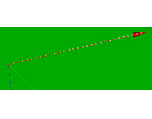
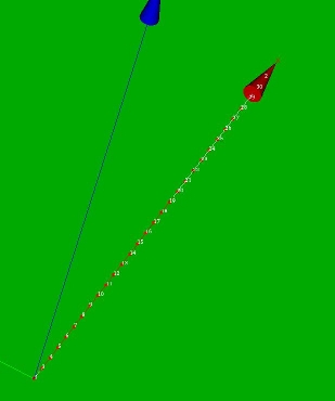
The configuration of the beams: this mesh consists of about thirty beam elements distributed along the x axis.
Note that this has the curious effect that the coordinates of the nodes are defined by a single coordinate. A mesh along the y axis yields a 2D coordinate (x equal to zero). No prices for further guessing.
I decided to read the configuration mesh from unit 20, defined by ASTK:
#Read MED mesh file
BeamMesh=LIRE_MAILLAGE(UNITE=20,
                       FORMAT='MED',
                       NOM_MED='Mbeam1',
                       INFO_MED=2,
                       INFO=2,);
The cross section of the L shaped beam is read from unit 21, also defined by ASTK:
XL=LIRE_MAILLAGE(UNITE=21,
                       FORMAT='MED',
                       NOM_MED='AMesh',
                       INFO_MED=2,
                       INFO=2,);
In the pictures below the configuration and cross section meshes are shown.
-
 *
* 


The boundary conditions are: fully clamped at x = 0, free at the opposite end.
The load consist of a shear force of 1 [N] in y direction at the end node:
#Define boundary conditions
BndCnd=AFFE_CHAR_MECA(MODELE=BeamMod,
                     DDL_IMPO=(_F(GROUP_NO='P1',DX=0.0, DY=0.0, DZ=0.0,
                                  DRX=0.0,DRY=0.0,DRZ=0.0,),),
                     FORCE_NODALE=_F(GROUP_NO='P2',FX=0.0,FY=1.0,FZ=0.0),);
Using the macro MACR_CARA_POUTRE
As seen previously, the cross section of the L shaped beam is read from unit 21, also defined by ASTK:
XL=LIRE_MAILLAGE(UNITE=21,
                       FORMAT='MED',
                       NOM_MED='AMesh',
                       INFO_MED=2,
                       INFO=2,);
The result structure XL is used by the macro MACR_CARA_POUTRE to retrieve the cross section quantities of it:
Bsection=MACR_CARA_POUTRE(MAILLAGE=XL,
                         INFO=2,
                         ORIG_INER=(0.0,0.0),);
The result Bsection is an Aster (table Bsection:<table_sdaster(7f166f039810,'Bsection')> with a number of components.
The table can be written to a file to be examined:
IMPR_TABLE(TABLE=Bsection,
           FORMAT='TABLEAU',
           UNITE=26,
           SEPARATEUR=' * ',
           TITRE='xsection of L-beam');
#
# -------------------------------------------------------------------------#
#xsection of L-beam
#ASTER 10.02.00 CONCEPT Bsection CALCULE LE 26/03/2011 A 15:57:43 DE  TYPE
#TABLE_SDASTER
* LIEU         * ENTITE       * AIRE_M       * CDG_X_M      * CDG_Y_M
* IX_G_M       * IY_G_M       * IXY_G_M      * Y_MAX        * Z_MAX
* Y_MIN        * Z_MIN        * R_MAX        * AIRE         * CDG_X
* CDG_Y        * IX_G         * IY_G         * IXY_G        * IY_PRIN_G
* IZ_PRIN_G    * ALPHA        * X_P          * Y_P          * IX_P
* IY_P         * IXY_P        * IXR2         * IYR2         * IYR2_PRIN_G
* IZR2_PRIN_G  * IXR2_P       * IYR2_P       * MAILLAGE
* .9000014
* .9000014     * TOUT         *  1.54334E-03 *  1.14339E-02 *  3.95862E-02
*  1.53931E-06 *  2.14464E-07 * -2.96934E-07 *  6.14691E-02 *  1.94603E-02
* -4.67767E-02 * -3.03799E-02 *  6.14862E-02 *  1.54334E-03 *  1.14339E-02
*  3.95862E-02 *  1.53931E-06 *  2.14464E-07 * -2.96934E-07 *  1.50958E-07
*  1.60282E-06 *  1.02072E+02 *  0.00000E+00 *  0.00000E+00 *  3.95783E-06
*  4.16232E-07 *  4.01622E-07 *  1.10571E-08 *  6.24183E-09 * -8.41633E-09
*  9.50713E-09 *  2.99290E-07 *  3.76498E-08 * -
Now suppose you need the area of the cross section AIRE/AIRE_M. This is the third entry (and equal to entry 14 AIRE) of the table. The numerical value is 1.54334E-03 [mm2].
Other interesting quantities are:
- CDG_X_M and CDG_X_M:
- centre of gravity CoG/CDG in x and y direction
- Y_MIN/MAX and Z_MIN/Max:
- minimum and maximum distance from CDG in the main coordinate system 0YZ. The origin coincides with CoG/CDG and is rotated by alpha
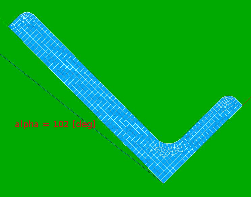
- ALPHA:
- rotation (in [deg]) from global x axis of the mesh to local Y axis of the main coordinate system. In this case alpha = 102 [deg], see also second picture.
- IY_PRIN_G and IZ_PRIN_G:
- main <how is this called in english?> lijntraagheidsmomenten
For normal static analysis we only need the torsion stiffness of the beam. This is not provided by the table.
This table can be accessed as follows:
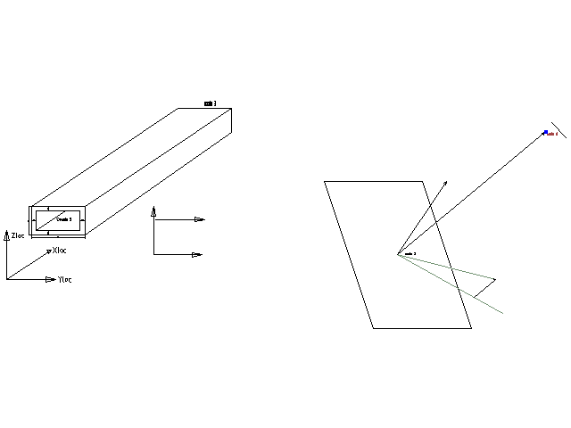
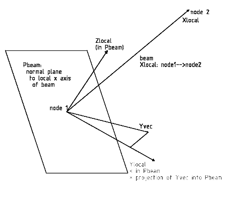
General way to define the orientation of the beam
The geometry and mesh are generated in Salome in the standard way. In Code Aster the mesh is read, including nodes number, node coordinates, element types and element connectivity. We use linear seg2 elements for the beams.
Of each element we can
- determine the nodes by the connectivity matrix,
- determine the x coordinates of the nodes and
- generate the orientation of the beam
by Python commands.
-
 *
* 
-
 *
*


Define a beam element by standard commands
After reading the mesh file the following two commands define the beam elements in a standard way:
#Assign to the Model
BeamMod=AFFE_MODELE(MAILLAGE=BeamMesh,
                   AFFE=_F(##TOUT='OUI',
                           GROUP_MA='beam1',
                           PHENOMENE='MECANIQUE',
                           MODELISATION='POU_D_T',),);