Difference between revisions of "Contrib:KeesWouters/bc/pythonlist"
Keeswouters (Talk | contribs) m (→Adding the boundary conditions to the calculation) |
Keeswouters (Talk | contribs) m (→Python code for list for free rotation) |
||
| Line 78: | Line 78: | ||
ElemList = list(PyMesh.correspondance_mailles) | ElemList = list(PyMesh.correspondance_mailles) | ||
ElemType = list(PyMesh.tm) | ElemType = list(PyMesh.tm) | ||
| − | NodeGroup = PyMesh.gno ## list of GROUP_NO groups (see help( | + | NodeGroup = PyMesh.gno ## list of GROUP_NO groups (see help(MAIL_PY) for object methods reference) |
ElemGroup = PyMesh.gma ## list of GROUP_MA groups, eg groupstr | ElemGroup = PyMesh.gma ## list of GROUP_MA groups, eg groupstr | ||
Revision as of 09:59, 27 January 2013
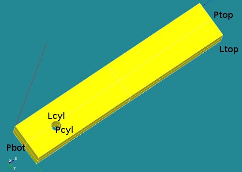
Geometry and mesh of the block with cylindrical hole
Applied on a simple block with a cylindrical hole the use of LIAISON_DLL is shown to simulate a cylindrical coordinate system
Contrib:KeesWouters/bc/cylinder
Geometry and mesh of the block with cylindrical hole
- key words
    o LIAISON_DDL
    o simulated cylinder coordinates and boundary conditions
Contrib:KeesWouters/bc/pythonlist
Rotation axis defined by Python list
- key words
    o LIAISON_DDL
    o simulated cylinder coordinates and boundary conditions
    o Python list for applying boundary conditions
Contents
Geometry and mesh of the block with cylindrical hole
This contribution depends on the construction defined here.
So please this contribution to find out the general behaviour of the construction: geometry, material properties and boundary conditions are given there.
If you would like to run this calculation, please use this one, since it is much easier (no copy and paste). It does however need some Python resources that need to be available. Does it sound like a warning? Guess not.
This construction shows the use of LIAISON_DDL to simulate boundary condition on a cylindrical hole. It just shows the use of it: -the code is far from general. This may be improved in future versions.
Some images of the construction:
-
 *
* 


A number of groups has been defined (P for plane, L for line segments):
- Ptop (not used)
- Pbot (not used)
- Pcyl (could be used to define nodes on this surface)
- Lcyl (not used in final version) and
- Ltop, used to apply boundary conditions in x and y direction.
The boundary conditions in detail
- The first boundary condition on the line segment Ltop is easy to define:
- bcforce=AFFE_CHAR_MECA(MODELE=Cmod,DDL_IMPO=(_F(GROUP_MA='Ltop',DY=0.5,DX=0.0000),),);
- The cylindrical boundary condition on the nodes of the cylindrical hole are defined by the LIAISON_DDL keyword in stead of DDL_IMPO:
- ... LIAISON_DDL=(_F(NOEUD=('Ni','Ni','Ni'),DDL=('DX','DY','DZ'),COEF_MULT=(alpha1,alpha2,alpha3),COEF_IMPO=beta),
Using this keyword and selecting all the nodes for Ni can simulate a tangential boundary condition.
- ... LIAISON_DDL=(_F(NOEUD=('Ni','Ni','Ni'),DDL=('DX','DY','DZ'),COEF_MULT=(alpha1,alpha2,alpha3),COEF_IMPO=beta),
Now remember that the part in the _F(...) operator can be placed in a Python list, dictionary, or tuple, eg:
_F(NOEUD=('N1','N1','N1'),DDL=('DX','DY','DZ'),COEF_MULT=(0.00,0.00,0.45),COEF_IMPO=0.00)
:::::::
_F(NOEUD=('N808','N808','N808'),DDL=('DX','DY','DZ'),COEF_MULT=(0.0, -0.36, -0.26),COEF_IMPO=0.00)
is the same as, or equivalent to:
{'NOEUD': ['N1',  'N1',  'N1'  ],'COEF_MULT':[0.00,0.00, 0.45], 'COEF_IMPO':0.0,'DDL':['DX', 'DY', 'DZ']}
:::::
{'NOEUD': ['N808','N808','N808'],'COEF_MULT':[0.0,-0.36,-0.26], 'COEF_IMPO':0.0,'DDL':['DX','DY','DZ']}
Alright, it took me several days to find out just this. But once you know, it is easy.
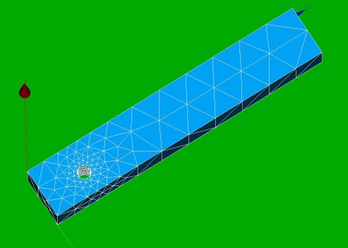
Now just an image to recall why we need to restrict these degrees of freedom:

Remarks
- here I included the dof 'DX' with a coefficient alpha1 = 0.0 to make the script more general. The coefficient alpha1 is zero here because the axis of rotation is along the x-axis.
Python code for list for free rotation
Since we are going to use plane Python script language, we need to define:
DEBUT(PAR_LOT='NON')
We will also use the some modules defined in the ...Utilitai.partition folder:
from Utilitai.partition import *
PyMesh   = MAIL_PY()                 ## convert CodeAster mesh to Python
PyMesh.FromAster(mesh);
nonu     = PyMesh.dime_maillage[0]   ## number of nodes
elnu     = PyMesh.dime_maillage[2]   ## number of elements
test=CmeshCA.dime_maillage[5]        ## [min,max] dimension: [0,5]
NodeCoord    = PyMesh.cn             ## xyz coordinates of nodes (nonu*3 matrix)
ElemConnect  = PyMesh.co             ## node numbers of elements (elnu*x matrix)
NodeList = list(PyMesh.correspondance_noeuds)
ElemList = list(PyMesh.correspondance_mailles)
ElemType = list(PyMesh.tm)
NodeGroup = PyMesh.gno               ## list of GROUP_NO groups (see help(MAIL_PY) for object methods reference)
ElemGroup = PyMesh.gma               ## list of GROUP_MA groups, eg groupstr
This part of the script extract the nodes and coordinates of the cylinder area that need to have the rotational degrees of freedom. Note that this group of nodes has already been defined in Salome. The group is called 'Ncyl'
  NodeCount = 0
  ddl_condition=[]                   ## initialise ddl_condition list
  for ii in xrange(len(NodeGroup[groupstr])):
     NodeNumber = NodeGroup[groupstr][ii]
     #print 'NodeGroup: ',ii,NodeNumber,NodeCount
     NodeCount+=1
     NNxyz = NodeCoord[NodeNumber]
     nx,ny,nz = cylinder_normal(P1,P2,NNxyz)
     NodeCount+=1
     NNp1 = NodeNumber+1         # node numbers are increased by 1: Salome <--> Code Aster
     ddl_condition.append({'NOEUD': ['N%d'%(NNp1),'N%d'%(NNp1),'N%d'%(NNp1)], 'DDL':['DX','DY','DZ'], 'COEF_MULT': [nx,ny,nz],'COEF_IMPO':0.00})
     if info>1:
        #print {'NOEUD': ['N%d'%(NNp1),'N%d'%(NNp1),'N%d'%(NNp1)], 'DDL':['DX','DY','DZ'], 'COEF_MULT': [0.0,ny-y1,nz-z1],'COEF_IMPO':0.00}
        print ddl_condition[ii]
  if info>0:
    # check format of bc_list
    print ic,countntop,': ',ddl_condition[0]
    print '::::::::::::::::::::::::::'
    print ic,countntop,': ',ddl_condition[-1]
The AFFE_CHAR_MECA part can be compared to this (small part of the extraction) in the standard way:
ddl_condition=AFFE_CHAR_MECA(MODELE=Cmod,
     LIAISON_DDL =
       _F(NOEUD=('N162 ','N162 '),DDL=('DY','DZ'),COEF_MULT=( 0.312402110475 , -10.3238902922 ),COEF_IMPO=0.00),
       _F(NOEUD=('N12  ','N12  '),DDL=('DY','DZ'),COEF_MULT=( 0.0            , -9.55          ),COEF_IMPO=0.00),
       _F(NOEUD=('N695 ','N695 '),DDL=('DY','DZ'),COEF_MULT=(-0.443605677987 , -9.92440897899 ),COEF_IMPO=0.00),
       ...
       _F(NOEUD=('N765 ','N765 '),DDL=('DY','DZ'),COEF_MULT=(-0.162737538758 , -10.4195431962 ),COEF_IMPO=0.00),
       _F(NOEUD=('N551 ','N551 '),DDL=('DY','DZ'),COEF_MULT=( 0.107926195474 , -9.56313396066 ),COEF_IMPO=0.00),),);
Now the list can be used in the AFFE_CHAR_MECA command just as the _F(...) operator:
rotcyl=AFFE_CHAR_MECA(MODELE=Cmod,LIAISON_DDL = ddl_condition);
Adding the boundary conditions to the calculation
Finally, the list is applied to the MECA_STATIQUE command.
result=MECA_STATIQUE(MODELE=Cmod,
                  CHAM_MATER=Amat,
                  EXCIT=(_F(CHARGE=bcforce,),
                         _F(CHARGE=rotcyl),),);
Updated comm file for Code-Aster v11
updated january 2013
Code-Aster evolves, so a lot of commands have changed since v9-10 of Code Aster. The input files for v11 reflect these changes as well as some node selection.
Since we have to import a few Python files to define the rotation, in DEBUT we need to advice Code-Aster to talk to Python in an proper way:
DEBUT(PAR_LOT='NON');
import sys
sys.path.append("/cae_sg500/caexample/caelinux/csys1/python2a") ## define your own path here for import RotationAxisBC
from CA_geometry import RotationAxisBC
import numpy
The selection of nodes on the cylinder is now included in the command file:
Cmesh=LIRE_MAILLAGE(UNITE=20,FORMAT='MED',);
Cmesh=DEFI_GROUP(reuse =Cmesh,
                 MAILLAGE=Cmesh,
                 CREA_GROUP_NO=_F(NOM='Ncyl',GROUP_MA='Pcyl',),);
The geometry group Pcyl [GROUP_MA='Pcyl'] need to be defined in the mesh file. This is easy in eg Salome. The selection of the node group GROUP_NO='Ncyl', previously done in Salome, is now carried out by the DEFI_GROUP command (which I find easier).
Now returning to the definition of the free rotation of a cylinder around its axis: two points P1 and P2 define the centre line of the rotation axis (which may coincide with the centre axis of a cylinder). Ideally, these two point would be based on the selection of nodes, but so far I have figured out how to do that relatively easy.
Anyway, the points P1 and P1 are numpy arrays and define the rotation axis. The Python function RotationAxisBC(...) has five arguments:
- mesh: Cmesh
- group of nodes GROUP_NO 'Ncyl' that are restriction to rotate around the given axis
- two points: numpy arrays, P1 and P2 defining the rotation axis and
- info: [0|1|2] for printing controle
P1 = numpy.array([0.0, 2.0, 3.0])
P2 = numpy.array([2.0, 2.0, 3.0])
info = 0
ddl_condition = RotationAxisBC(Cmesh,'Ncyl',P1,P2,info)
rotcyl = AFFE_CHAR_MECA(MODELE=Cmod,LIAISON_DDL=ddl_condition);
The result is a Python list ddl_condition that contains the familiar parts of the LIAISON_DDL for all the nodes contained in the selection 'Ncyl'.
As always, the hard work is being done by the Python function RotationAxisBC(...). More on this later ..., see for now the download files.
Note that the CALC_ELEM procedure has been made obsolete.
Input files for the FE Analysis
Download the files here:
- >>>Media:kw_blockrot_pythonlist.zip for C-Aster version 10-
- >>>Media:kw_rotation_cylinder_ca11.zip for C-Aster version 11
Input files:
- Python script for defining the geometry and mesh (blockrot4.py), load by File --> load script (cntrl T in the object browser), refresh (F5) after running
- Save the mesh file by right clicking in the object browser by right clicking on the mesh name Mbcyl; select Export to MED and accept or change the default values (v11 saves mesh file automaticly in working directory)
- ASTK file (cylrot.astk, you need to edit the path to your requirements ...)
- command file (blockb.comm)
- blockrot6.py basicly construct the geometry and selects nodes on the cylinder. blockrot6.py directly selects the nodes on the cylinder area by filters. See also [Salome] for more reference (and thank you JMB for the question asked there).
References
CodeAster documentation:
[Document u4.44.01 - AFFE_CHAR_MECA, page 20/109]
[Document u1.03.02 - Methodes Python d'access aux objects Aster - french]
CodeAster forum:
[Using python with Aster]
[Applying nodal forces node by node]
[Accessing Mesh Data Structure]