Contrib:KeesWouters/bc/cylinder
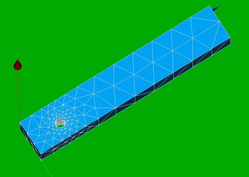
Geometry and mesh of the block with cylindrical hole
Applied on a simple block with a cylindrical hole the use of LIAISON_DLL is shown to simulate a cylindrical coordinate system
Contrib:KeesWouters/bc/cylinder
Geometry and mesh of the block with cylindrical hole
- key words
    o LIAISON_DDL
    o simulated cylinder coordinates and boundary conditions
Contrib:KeesWouters/bc/pythonlist
Rotation axis defined by Python list
- key words
    o LIAISON_DDL
    o simulated cylinder coordinates and boundary conditions
    o Python list for applying boundary conditions
Contents
Geometry and mesh of the block with cylindrical hole
This construction shows the use of LIAISON_DDL to simulate boundary condition on a cylindrical hole. It just shows the use of it: -the code is far from general. This may be improved in future versions.
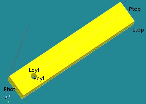
The geometry consists of a block with a cylindrical hole near the bottom side. The overall dimensions of the block are [Lx * Ly * Lz] = [2.0 * 3.5 * 20.0 ]. The hole is placed on the x-plane at position [yc, zc] = [2.0, 3.0]. The radius of the hole is R=0.45.
-
 *
* 


A number of groups has been defined (P for plane, L for line segments):
- Ptop (not used)
- Pbot (not used)
- Pcyl (could be used to define nodes on this surface)
- Lcyl (not used in final version) and
- Ltop, used to apply boundary conditions in x and y direction.
Material properties of the block
The material property of the block is set to steel.
The boundary conditions
- On the top line segment Ltop a non zero displacement in y direction is prescribed. The displacement is z direction is fixed.
- On the nodes connected to the cylindrical hole a tangential displacement is allowed. The radial component is fixed. The displacement in axial or x direction is free. Due to this restriction the displacement of the geometry in z direction is defined.
The boundary conditions in detail
- The first boundary condition on the line segment Ltop is easy to define:
- bcforce=AFFE_CHAR_MECA(MODELE=Cmod,DDL_IMPO=(_F(GROUP_MA='Ltop',DY=0.5,DX=0.0000),),);
- The cylindrical boundary condition on the nodes of the cylindrical hole are defined by the LIAISON_DDL keyword in stead of DDL_IMPO:
- ... LIAISON_DDL=(_F(NOEUD=('Ni','Ni'),DDL=('DY','DZ'),COEF_MULT=(alpha1,alpha2),COEF_IMPO=beta),
Using this keyword and selecting all the nodes for Ni can simulate a tangential boundary condition. Details follow now.
- ... LIAISON_DDL=(_F(NOEUD=('Ni','Ni'),DDL=('DY','DZ'),COEF_MULT=(alpha1,alpha2),COEF_IMPO=beta),
With LIAISON_DDL it is possible to couple displacements of various nodes to each other. The general form is:
- sum(alpha(i)*du(j)_node(k)) = beta, sum over all alpha(i)
- alpha(i) is a given value, du(j)_node(k) is the displacement compoment du(j) (dx, dy, dz, and possibly drx, dry, drz) of node k
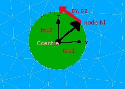
- To restrict the displacement of a node in a given direction, we use the fact that the inner product of two perpendicular vectors are zero. Hence defining a vector tau perpendicular to an allowed displacement is suitable for this purpose.
- from the prevous it follows that tau is a vector in the restricted direction.
- For this case: we define a vector tau in the radial direction of the cylinder and the allowable displacement is perpendicular to this, ie tangential to the cylinder surface. Now make this concrete with the LIAISON_DDL keyword.
- The LIAISON_DDL keyword with NOEUD defines the following restriction for the slightly more general case:
- LIAISON_DDL=(_F(NOEUD=('Ni','Nj'),DDL=('DY','DZ'),COEF_MULT=(alpha1,alpha2),COEF_IMPO=beta),
- component 'DY' of node 'Ni' --> dy_ni
- component 'DZ' of node 'Nj' --> dz_nj
- alpha1*dy_ni + alpha2*dz_nj = beta
So if we choose alpha1 and alpha2 the components of the vector from the centre of the cylindrical hole to the node itself,
say tau = [tau1,tau2] = [(ynode-yc), (znode-zc)], - [alpha1,alpha2] = [tau1,tau2] and putting beta to zero we have:
- <[tau1,tau2],[DY,DZ]>=0.
- This means we effectively have: tau1*DY=-tau2*DZ or a tangential restriction of the movement around the cylinder centre.
- LIAISON_DDL=(_F(NOEUD=('Ni','Nj'),DDL=('DY','DZ'),COEF_MULT=(alpha1,alpha2),COEF_IMPO=beta),
-
 * :
* : 


Remarks
- the selection of the cylindrical coordinate system is severly restricted here. It should be relatively easy to implement a general cylindrical coordinate system by selecting two points that define the centre axis and a radius. But I really need to activate Numpy first before I try. Although it should work on Salome5.1.4 ...
- the output by the Python script needs to be improved. That I will call work in progress.
- In stead of looping through all the nodes, preselecting the nodes on the cylinder by a filter (already done) is possible. But at the moment I cannot access the selected nodes (again that means I donot know how to, see also Python script at the end).
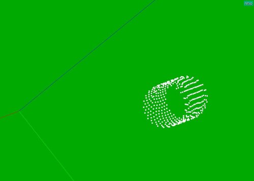
Selection of the nodes (Salome)
As usual, the geometry and mesh are defined by a Python script. This makes it relatively easy to select the nodes on the cylinder face. The following snippet of the code selects the nodes and writes the keyword and corresponding LIAISON_DDL part to the Python output window:
...
y1 = 2
z1 = 3
...
Rcylinder = 0.45
Lcylinder = 2.00
...
countall=0
countcyl=0
node_oncyl = []
Rcyl2 = Rcylinder**2
eps = 1e-4
print "\ncopy and paste next part into command file",
print "\n******************************************\n"
print "cylco2=AFFE_CHAR_MECA(MODELE=Cmod,\n     LIAISON_DDL = (",
for allnode in Mbcyl.GetNodesId():
   countall+=1
   q1, q2, q3 = Mbcyl.GetNodeXYZ(allnode)
   # on cylinder yes/no:
   dy2 = (q2-y1)**2
   dz2 = (q3-z1)**2
   if abs(dy2+dz2-Rcyl2)<eps:
      countcyl+=1
      cnode = to_string(allnode)
      node_oncyl.append(allnode)
      #ss = []
      ss = "\n          _F(NOEUD=('N"+cnode+"','N"+cnode+"'),DDL=('DY','DZ'),COEF_MULT=("
      print ss,
      print (q2-y1),
      print ",",
      print (q3-z1),
      print "),COEF_IMPO=0.00),",
   pass
pass
print "),);"
print "\nend of copy and past",
print "\n********************\n\n\n"
the main part of the code print output to the Python console in a suitable formatted way.
Copy and paste the indicated output from the Python console into the C-A command file:
All should run fine. Well, it did here after more than a few tries. It looks like:
cylco2=AFFE_CHAR_MECA(MODELE=Cmod,
     LIAISON_DDL =
       _F(NOEUD=('N162 ','N162 '),DDL=('DY','DZ'),COEF_MULT=( 0.312402110475 , -10.3238902922 ),COEF_IMPO=0.00),
       _F(NOEUD=('N12  ','N12  '),DDL=('DY','DZ'),COEF_MULT=( 0.0            , -9.55          ),COEF_IMPO=0.00),
       _F(NOEUD=('N695 ','N695 '),DDL=('DY','DZ'),COEF_MULT=(-0.443605677987 , -9.92440897899 ),COEF_IMPO=0.00),
       ...
       _F(NOEUD=('N765 ','N765 '),DDL=('DY','DZ'),COEF_MULT=(-0.162737538758 , -10.4195431962 ),COEF_IMPO=0.00),
       _F(NOEUD=('N551 ','N551 '),DDL=('DY','DZ'),COEF_MULT=( 0.107926195474 , -9.56313396066 ),COEF_IMPO=0.00),),);
The results of the calculation
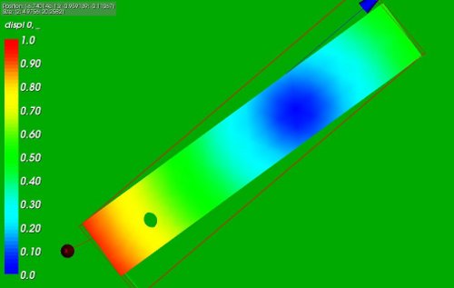
The following picture show the rotation of the block around the cylindrical hole:

- The left part of the picture displays the von Mises stresses in the construction: they are zero to the working precision as we expect. The rotation around the cylinder is controlled by the displacement at the top edge and can be performed by a rigid body movement.
- The right part shows the displacement in y direction: the construction nicely rotates around the cylindrical hole.
A bit of fooling around ...
Selecting the same nodes around the cylindrical hole but choosing the rotating point with an offset of 10 in z direction yields the following displacement:
* 

The code to generate this during the Salome session:
...
zoffset = 10.0  ## change to 10.0 for second picture
...
for allnode in Mbcyl.GetNodesId():
   countall+=1
   q1, q2, q3 = Mbcyl.GetNodeXYZ(allnode)
   # on cylinder yes/no:
   dy2 = (q2-y1)**2
   dz2 = (q3-z1)**2
   if abs(dy2+dz2-Rcyl2)<eps:
      countcyl+=1
      cnode = to_string(allnode)
      node_oncyl.append(allnode)
      #ss = []
      ss = "\n          _F(NOEUD=('N"+cnode+"','N"+cnode+"'),DDL=('DY','DZ'),COEF_MULT=("
      print ss,
      print (q2-y1),
      print ",",
      print (q3-z1-zoffset),
      print "),COEF_IMPO=0.00),",
   pass
pass
Input files for the FE Analysis and references
Input files:
- Python script for defining the geometry and mesh (blockrot4.py), load by File --> load script (cntrl T in the object browser), refresh (F5) after running
- Save the mesh file by right clicking in the object browser by right clicking on the mesh name Mbcyl; select Export to MED and accept or change the default values
- ASTK file (cylrot.astk, you need to edit the path to your requirements ...)
- command file (blockb.comm)
Download the files here:
- blockrot4.py and blockrot6.py basicly perform the same operation: selecting nodes on the cylinder. Though the way it is implemented is quite different: blockrot4 depends on the measures of the geometry whereas blockrot6 directly selects the nodes on the cylinder area by filters. See also [Salome] for more reference (and thank you JMB for the question asked there).
- blockrot7.py writes the liaison_ddl information to a file. Remember to change the path at line 109 to a suitable value for your system.
Reference:
[AFFE_CHAR_MECA, page 20/109]