Contrib:KeesWouters/bc/cylinder
- Applying cylinder boundary conditions
Applied on a simple block with a cylindrical hole the use of LIAISON_DLL is used to show the simulation of a cylindrical coordinate system
Contrib:KeesWouters/bc/cylinder- key words
- LIAISON_DDL
- key words
Contents
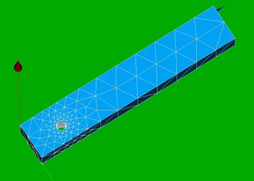
Geometry and mesh of the block with cylindrical hole
This is a very simple construction to show the use of LIAISON_DDL to simulate boundary condition on a cylindrical hole. It just shows the use of it: -the code is far from general. This may be improved in further versions.
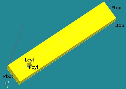
The geometry consists of a block with a cylindrical hole near the bottom side. The overall dimensions of the block are [Lx * Ly * Lz] = [2 * 3 * 20 ]. The hole is placed on the x-plane at position [yc, zc] = [2 3]. The radius of the hole is R=0.45.
-
 *
* 


A number of groups has been defined (P for plane, L for line segments):
- Ptop
- Pbot
- Pcyl
- Lcyl and
- Ltop
Material properties of the block
The material property of the block is set to steel.
The boundary conditions
- On the top line segment Ltop a non zero displacement in y direction is prescribed. The displacement is z direction is fixed.
- On the nodes connected to the cylindrical hole a tangential displacement is allowed. The radial component is fixed. The displacement in axial or x direction is free. Due to this restriction the displacement of the geometry in z direction is defined.
The boundary conditions in detail
- The first boundary condition on the line segment Ltop is easy to define:
- bcforce=AFFE_CHAR_MECA(MODELE=Cmod,DDL_IMPO=(_F(GROUP_MA='Ltop',DY=0.5,DX=0.0000),),);
- The cylindrical boundary condition on the nodes of the cylindrical hole are defined by the LIAISON_DDL keyword in stead of DDL_IMPO:
- ... LIAISON_DDL=(_F(NOEUD=('Ni','Ni'),DDL=('DY','DZ'),COEF_MULT=(alpha1,alpha2),COEF_IMPO=beta),
Using this keyword and selecting all the nodes for Ni can simulate a tangential boundary condition. Details follow now.
- ... LIAISON_DDL=(_F(NOEUD=('Ni','Ni'),DDL=('DY','DZ'),COEF_MULT=(alpha1,alpha2),COEF_IMPO=beta),
The LIAISON_DDL keyword with NOEUD defines the following restriction for the slightly more general case:
- LIAISON_DDL=(_F(NOEUD=('Ni','Nj'),DDL=('DY','DZ'),COEF_MULT=(alpha1,alpha2),COEF_IMPO=beta),
- component 'DY' of node 'Ni' --> dy_ni
- component 'DZ' of node 'Nj' --> dz_nj
- alpha1*dy_ni + alpha2*dz_nj = beta
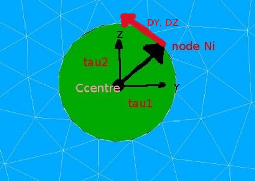
So if we choose alpha1 and alpha2 the components of the vector from the centre of the cylindrical hole to the node itself,
say tau = [tau1,tau2] = [(ynode-yc), (znode-zc)], - [alpha1,alpha2] = [tau1,tau2] and putting beta to zero we have:
- <[tau1,tau2],[DY,DZ]>=0.
- This means we effectively have: tau1*DY=-tau2*DZ or a tangential restriction of the movement around the cylinder centre.
-
 * :
* : 


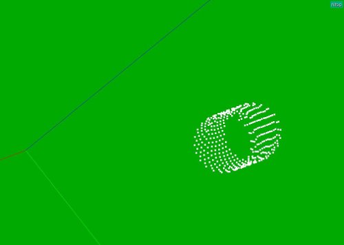
Selection of the nodes (Salome)
As usual, the geometry and mesh is defined by a Python script. This makes it relatively easy to select the nodes on the cylinder face. The following snippet of the code selects the nodes and writes the keyword and corresponding LIAISON_DDL part to the Python output window:
...
y1 = 2
z1 = 3
...
Rcylinder = 0.45
Lcylinder = 2.00
...
countall=0
countcyl=0
node_oncyl = []
Rcyl2 = Rcylinder**2
eps = 1e-4
for allnode in Mbcyl.GetNodesId():
   countall+=1
   q1, q2, q3 = Mbcyl.GetNodeXYZ(allnode)
   # on cylinder yes/no:
   dy2 = (q2-y1)**2
   dz2 = (q3-z1)**2
   if abs(dy2+dz2-Rcyl2)<eps:
      countcyl+=1
      node_oncyl.append(allnode)
      ##print countall,countcyl,allnode,q1,q2,q3
      print "_F(NOEUD=('N",
      print allnode,
      print "','N",
      print allnode,
      print "'),DDL=('DY','DZ'),COEF_MULT=(",
      print (q2-y1),
      print ",",
      print (q3-z1-10),
      print "),COEF_IMPO=0.00),"
   pass
pass
The output is not pretty and the space between 'N' and the node number needs to be discarded. I still have to improve my Python knowledge ;-).
The copy and paste the output, together with the two lines below in the C-A command file:
cylco2=AFFE_CHAR_MECA(MODELE=Cmod,
        LIAISON_DDL = (
add ,); at the end of the command and all should run fine. Well, it did here after more than a few tries. It looks like:
cylco2=AFFE_CHAR_MECA(MODELE=Cmod,LIAISON_DDL =
_F(NOEUD=('N162 ','N162 '),DDL=('DY','DZ'),COEF_MULT=( 0.312402110475 ,  -10.3238902922 ),COEF_IMPO=0.00),
_F(NOEUD=('N12  ','N12  '),DDL=('DY','DZ'),COEF_MULT=( 0.0            , -9.55          ),COEF_IMPO=0.00),
_F(NOEUD=('N695 ','N695 '),DDL=('DY','DZ'),COEF_MULT=( -0.443605677987 , -9.92440897899 ),COEF_IMPO=0.00),
...
_F(NOEUD=('N765 ','N765 '),DDL=('DY','DZ'),COEF_MULT=( -0.162737538758 , -10.4195431962 ),COEF_IMPO=0.00),
_F(NOEUD=('N551 ','N551 '),DDL=('DY','DZ'),COEF_MULT=( 0.107926195474 , -9.56313396066 ),COEF_IMPO=0.00),),);
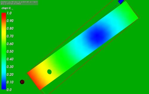
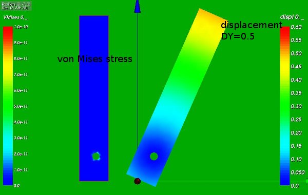
The results of the calculation
The following picture show the rotation of the block around the cylindrical hole:
-
 *
*