Difference between revisions of "Contrib:KeesWouters/bc/cylinder"
From CAELinuxWiki
Keeswouters (Talk | contribs) m (→''The boundary conditions in detail'') |
Keeswouters (Talk | contribs) m (→''The boundary conditions in detail'') |
||
| Line 40: | Line 40: | ||
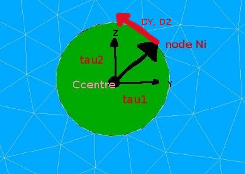
*** <[tau1,tau2],[DY,DZ]>=0. This means we effectively have: tau1*DY=-tau2*DZ or a tangential restriction of the movement around the cylinder centre. | *** <[tau1,tau2],[DY,DZ]>=0. This means we effectively have: tau1*DY=-tau2*DZ or a tangential restriction of the movement around the cylinder centre. | ||
| − | : [[image:kw_bcylnodes.jpg]] | + | : [[image:kw_bcylnodes.jpg]] * : [[image:kw_bcylhole1.jpg]] |
Revision as of 16:30, 7 August 2010
- Applying cylinder boundary conditions
Applied on a simple block with a cylindrical hole the use of LIAISON_DLL is used to show the simulation of a cylindrical coordinate system
Contrib:KeesWouters/bc/cylinder- key words
- LIAISON_DDL
- key words
Contents
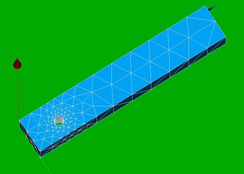
Geometry and mesh of the block with cylindrical hole
This is a very simple construction to show the use of LIAISON_DDL to simulate boundary condition on a cylindrical hole. It just shows the use of it: -the code is far from general. This may be improved in further versions.
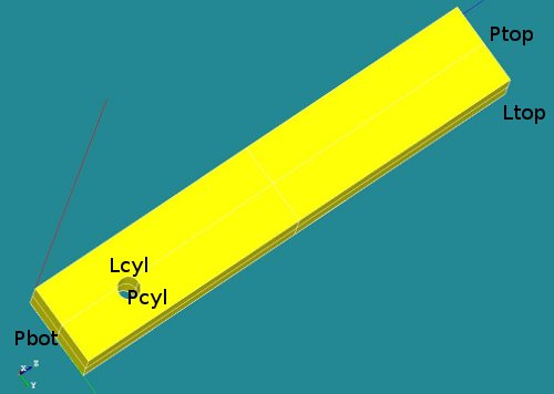
The geometry consists of a block with a cylindrical hole near the bottom side. The overall dimensions of the block are [Lx * Ly * Lz] = [2 * 3 * 20 ]. The hole is placed on the x-plane at position [yc, zc] = [2 3]. The radius of the hole is R=0.45.
-
 *
* 


A number of groups has been defined (P for plane, L for line segments):
- Ptop
- Pbot
- Pcyl
- Lcyl and
- Ltop
Material properties of the block
The material property of the block is set to steel.
The boundary conditions
- On the top line segment Ltop a non zero displacement in y direction is prescribed. The displacement is z direction is fixed.
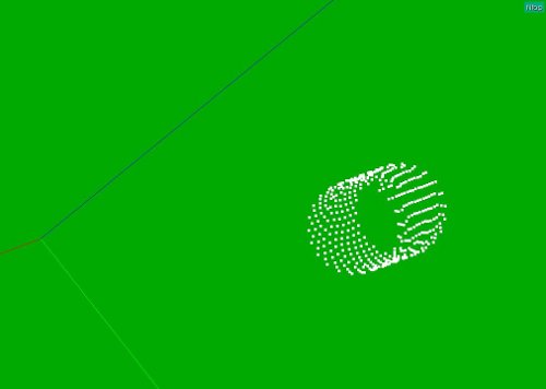
- On the nodes connected to the cylindrical hole a tangential displacement is allowed. The radial component is fixed. The displacement in axial or x direction is free. Due to this restriction the displacement of the geometry in z direction is defined.
The boundary conditions in detail
- The first boundary condition on the line segment Ltop is easy to define:
- bcforce=AFFE_CHAR_MECA(MODELE=Cmod,DDL_IMPO=(_F(GROUP_MA='Ltop',DY=0.5,DX=0.0000),),);
- The cylindrical boundary condition on the nodes of the cylindrical hole are defined by the LIAISON_DDL keyword in stead of DDL_IMPO:
- ... LIAISON_DDL=(_F(NOEUD=('Ni','Ni'),DDL=('DY','DZ'),COEF_MULT=(alpha1,alpha2),COEF_IMPO=beta),
Using this keyword and selecting all the nodes for Ni can simulate a tangential boundary condition. Details follow now.
- ... LIAISON_DDL=(_F(NOEUD=('Ni','Ni'),DDL=('DY','DZ'),COEF_MULT=(alpha1,alpha2),COEF_IMPO=beta),
The LIAISON_DDL keyword with NOEUD defines the following restriction for the slightly more general case:
- LIAISON_DDL=(_F(NOEUD=('Ni','Nj'),DDL=('DY','DZ'),COEF_MULT=(alpha1,alpha2),COEF_IMPO=beta),
- component 'DY' of node 'Ni' --> dy_ni
- component 'DZ' of node 'Nj' --> dz_nj
- alpha1*dy_ni + alpha2*dz_nj = beta
So if we choose alpha1 and alpha2 the components of the vector from the centre of the cylindrical hole to the node itself,
say tau = [tau1,taut2] = [(ynode-yc), (znode-zc)] and putting beta to zero we have:- <[tau1,tau2],[DY,DZ]>=0. This means we effectively have: tau1*DY=-tau2*DZ or a tangential restriction of the movement around the cylinder centre.
-
 * :
* :