Difference between revisions of "Contrib:KeesWouters/spring"
Keeswouters (Talk | contribs) m (→'''Download input and output files''') |
m (→''Remarks'') |
||
| Line 121: | Line 121: | ||
===''Remarks''=== | ===''Remarks''=== | ||
A few personal notes: | A few personal notes: | ||
| − | * So for both the distributed line and the pressure you need to determine the | + | * So for both the distributed line and the pressure you need to determine the length of the segment and the area where the pressure is being applied. |
* For nodal forces the given force is applied at each node (FORCE_NODALE, FZ, trivial) | * For nodal forces the given force is applied at each node (FORCE_NODALE, FZ, trivial) | ||
* For a distributed line load the forces is per unit length (FORCE_ARETE, FZ, maybe not so trivial) and | * For a distributed line load the forces is per unit length (FORCE_ARETE, FZ, maybe not so trivial) and | ||
Revision as of 19:12, 24 July 2010
Contents
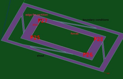
Spring construction
The spring construction consists of two rectangular plates with four spring leaves between them.
-
 *
* 


The outer rectangular plate shout together with the spring leaves consists of the same face. The inner rectangulare plate is a different face shin and has set different wall thickness in the C-A command file. The material for shout is set to brass and for shin steel. The thicknesses of the plates are 0.15 mm and 0.40 mm respectively. In the picture at the right hand side the transition between the two part is clearly visible with the straight mesh line.
In the python script the geometry and the mesh are defined: Media:kw_spring3py.zip.
To load it, in the Geometry module goto main menu File --> load script or ctrl T and select the file.
In this file you can see how the geometry is defined by:
- points to define the inner and outer rectangles and the spring positions
- lines between these points to define inner and outer rectangle and springs
- lines and wire to define the dividing between springs and inner rectangle (partitioning)
- partitioning of the outer rectangle and springs and inner rectangle
- grouping of the various elements:
- >> faces: outer rectangle and springs shout, inner rectangle shin
- >> lines for boundary conditions and forces: inedge, outedge
- >> nodes: node1 (N25), opposite nodes nodes13 (N25 and N28) and nodes4 (N25, N26, N27 and N28)
Applied loads on the inner plate
A number of loads will be applied on the inner plate of the construction in the out-of-plane (z direction) of the plate. The total force will always be 1 N. The following loads are applied:
- one force of 1 N at an corner node (N25) of the inner plate
- two forces of 0.5 N each at opposite corner nodes (N25 and N28) of the inner plate
- four forces of 0.25 N each at the corner (N25, N26, N27 and N28) of the inner plate
- a distributed line for at the inner edge of inner plate and
- a pressure on the inner plate
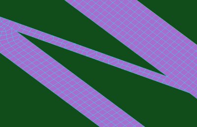
Orientation of the shells
In order to apply a pressure on a (shell) surface, all elements should be oriented in the same way. In order to show the effect of non oriented elements, in Salome I deliberaty reoriented some shell on the inner rectangle in a different direction, see figure below:

In Salome the upper and top surface of the elements are shown by a different colour, in this case green - blue and purple.
To orient all the shells of the inner and outer plate, use the following command in C-Aster:
meshmod=MODI_MAILLAGE(reuse=meshmod,
         MAILLAGE=meshmod,
         ORIE_NORM_COQUE=_F(GROUP_MA=('shout','shin',),
                            VECT_NORM= (0,0,+1),NOEUD='N924'),);
The key word ORIE_NORM_COQUE can be used with the following parameters:
- GROUP_MA: all the groups that need to be oriented, (mandatory)
- a normal vector VECT_NORM to indicate the desired direction of the shells and
- a node NOEUD where the normal vector is applied. If two groups are given, this should be on the border between the two groups shin and shout. All shells will be oriented continuously from this point onward in the given direction.
In this case the mess file indicates that 154 elements on the inner plate are reoriented:
TRAITEMENT DU GROUP_MA: shout    DE    2015 MAILLES 0 MAILLE(S) ONT ETE ORIENTEE(S)
TRAITEMENT DU GROUP_MA: shin     DE    1664 MAILLES 154 MAILLE(S) ONT ETE ORIENTEE(S)
AU TOTAL     154 MAILLE(S) ORIENTEE(S)
No reorientations yields the following error:
  !  group_ma  shin mailles mal orientees  72  !
  ....
  !  arret sur erreur(s), normale non sortante !
A few notes:
- In Salome, normally all shells are oriented in the same direction, but not necessarily in the direction you need.
- In this case: a normal vector in +z direction and a positive pressure yields a negative displacement of the inner plate, as expected.
- An in-plane normal vector [e.g VECT_NORM=(1.0,1.0,0.0,)] is indicated by C-Aster with the following error in the message file: ! le vecteur normal est dans le plan tangent !
Results
The various load cases
One force at inside corner applied
Applying one vertical force at a corner node (Fz = -1.00 N per node, 1 N total force), the vertical displacements at the four corner nodes are:
- dz at node N25: -0.423 mm
- dz at node N26: -0.191 mm
- dz at node N27: -0.177 mm and
- dz at node N28: +0.049 mm, i.e. average displacement in z direction is -0.21 mm.
The command for this is:
clamped=AFFE_CHAR_MECA(... ,FORCE_NODALE=_F(GROUP_NO='nodes1', FZ=-1.00,),);
Displacements - two forces at inside corners
Applying four vertical forces at the opposite corner nodes (Fz = -0.50 N per node, 1 N total force), the vertical displacements at the four corner nodes are:
- dz at nodes N26 and N27: -0.1840 mm and
- dz at nodes N25 and N28: -0.1870 mm (opposite nodes have the same values).
The command for this is:
clamped=AFFE_CHAR_MECA(... ,FORCE_NODALE=_F(GROUP_NO='nodes13', FZ=-0.50,),);
Four vertical forces applied
Applying four vertical forces at the corner nodes (Fz = -0.25 N per node, 1 N total force), the vertical displacements at the four corner nodes are:
- dz at nodes N25 and N28 -0.1855 and
- dz at nodes N26 and N27 -0.1856 (opposite nodes have the same values).
Roughly the same values as previously, and some additional bending of the inner plate.
The command for this is:
clamped=AFFE_CHAR_MECA(... ,FORCE_NODALE=_F(GROUP_NO='nodes4', FZ=-0.25,),);
Applying distributed line force along inner side
Applying one vertical force along the inner side of the small rectangle. The distributed force per unit length is -1/Linside, Linside is (3.4+5.4)*2 or 17.6 mm, total vertical force is once again -1.00 N. Then the vertical displacements at the four corner nodes are:
- dz at node N25 and N28: -0.1855 mm
- dz at node N26 and N27: -0.1856 mm.
The command for this is:
Linside = (3.4+5.4)*2
clamped=AFFE_CHAR_MECA(... ,FORCE_ARETE=_F(GROUP_MA='inedge', FZ=-1/Linside,),);
Applying a surface load on the inner plate
Finally we applying vertical pressure on the inner plate. The distributed load is now 1/Ain, where Ain is area of the inner plate: 16.64 mm2. The total vertical force is once again -1.00 N. Then the vertical displacements at the four corner nodes are:
- dz at node N25 and N28: -0.1854 mm
- dz at node N26 and N27: -0.1855 mm.
The command for this is:
Ain = 16.64
clamped=AFFE_CHAR_MECA(... ,FORCE_COQUE=_F(GROUP_MA='shin',PRES=1/Ain,),);
Displacement picture for single force and four forces
In the picture below the insideframe represents the single force on node N25. The green surface represents the four forces on the corner nodes. The other load cases are very much the same as this last one.

Note that the picture is upside down (positive z axis pointing downwards).
Top and bottom stresses for pressure load case
In the picture below the stresses sigma_yy in the top and bottom surface layers are given. Absolute values are about 650 MPa in the short spring. Not depicted are the stresses in the long spring. Here the relevant stress is sigma_xx and absolute maximum values have roughly the same value.

The bottom stresses are given in the surface representation, the top stresses are represented surfaceframe (with mesh).
The command file for calculating top and bottom stresses is a bit longer and is given at the end.
Remarks
A few personal notes:
- So for both the distributed line and the pressure you need to determine the length of the segment and the area where the pressure is being applied.
- For nodal forces the given force is applied at each node (FORCE_NODALE, FZ, trivial)
- For a distributed line load the forces is per unit length (FORCE_ARETE, FZ, maybe not so trivial) and
- For pressure the load is per unit area (FORCE_COQUE, PRES, trivial)
- The complete command for applying the forces is:
Linside  = (3.4+5.4)*2
Ain = 16.64
clamped=AFFE_CHAR_MECA(MODELE=modelc,
                     DDL_IMPO=(_F(GROUP_MA='outedge',DX=0.0,DY=0.0,DZ=0.0,),),
                      FORCE_COQUE=_F(GROUP_MA='shin',    PRES=1/Ain,),);
                     #FORCE_ARETE=_F(GROUP_MA='inedge',  FZ=-1/Linside,),);
                     #FORCE_NODALE=_F(GROUP_NO='node1',  FZ=-1.0,),);
                     #FORCE_NODALE=_F(GROUP_NO='nodes13',FZ=-0.50,),);
                     #FORCE_NODALE=_F(GROUP_NO='nodes4', FZ=-0.25,),);
Writing displacements to a table and text file
The displacements can be written to a file with the following C-A commands:
# define values for printing displacements at four inside corner nodes
meshmod=DEFI_GROUP(reuse =meshmod,
              MAILLAGE=meshmod,
              #CREA_GROUP_MA=_F(NOM='test',GROUP_MA=('outedge',),),
              CREA_GROUP_NO=_F(NOM='nforce',GROUP_NO='nodes4',),
              INFO=2,);
# define table TB_disp
TB_disp=POST_RELEVE_T(ACTION=(_F(OPERATION='EXTRACTION',
                             INTITULE='Displacements',
                             RESULTAT=result,
                             NOM_CHAM='DEPL',
                             TOUT_ORDRE='OUI',
                             GROUP_NO='nforce',
                             NOM_CMP=('DZ',),),),
                             #TOUT_CMP='OUI',
                             #RESULTANTE=('DZ',),),),
                     TITRE='DZ',);
# print displacements to file
IMPR_TABLE(TABLE=TB_disp,
         FORMAT='TABLEAU',
         UNITE=26,
         SEPARATEUR=' * ',
         TITRE='displacements at nodes',);
And the result file, defined in ASTK -see figure-
-
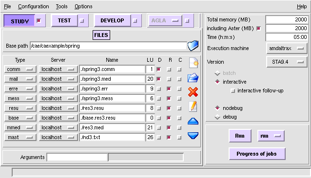
by mast-type, name ./nd3.txt and unit (LU) 26, looks as follows:

#
#---------------------------------------------------------------
#
#displacements at nodes
#DZ
* INTITULE      * NOEUD  * RESU     * NOM_CHAM   * NUME_ORDRE   * INST         * ABSC_CURV    * COOR_X       * COOR_Y       * COOR_Z       * DZ
* Displacements * N25    * result   * DEPL       *            1 *  0.00000E+00 *  0.00000E+00 *  2.30000E+00 *  2.30000E+00 *  0.00000E+00 * -1.85489E-01
* Displacements * N28    * result   * DEPL       *            1 *  0.00000E+00 *  6.38122E+00 *  7.70000E+00 *  5.70000E+00 *  0.00000E+00 * -1.85486E-01
* Displacements * N26    * result   * DEPL       *            1 *  0.00000E+00 *  9.78122E+00 *  7.70000E+00 *  2.30000E+00 *  0.00000E+00 * -1.85623E-01
* Displacements * N27    * result   * DEPL       *            1 *  0.00000E+00 *  1.61624E+01 *  2.30000E+00 *  5.70000E+00 *  0.00000E+00 * -1.85611E-01
Download input and output files
Download the following files:
- python script files defining geometry and mesh
- command files for Code Aster (stresses to be done ...)
- astk input file
- text file with nodal displacements of four nodes
- astk export file
- >>> Media:kw_spring3.zip
Note on Code Aster 10
Code Aster 10 is stricter then CA9- with respect to the MODI_MAILLAGE keyword in CREA_MAILLAGE. In case no TRIA6 or QUAD8 elements are available in the mesh, change line 23 in the command file:
meshmod=CREA_MAILLAGE(MAILLAGE=meshinit,
                     MODI_MAILLE=(_F(TOUT='OUI',OPTION='QUAD8_9',),
                                  _F(TOUT='OUI',OPTION='TRIA6_7',),),);
to, for QUAD8 mesh only:
meshmod=CREA_MAILLAGE(MAILLAGE=meshinit,
                     MODI_MAILLE=(_F(TOUT='OUI',OPTION='QUAD8_9',),),);
or, for TRIA6 mesh only:
 meshmod=CREA_MAILLAGE(MAILLAGE=meshinit,
                     MODI_MAILLE=(_F(TOUT='OUI',OPTION='TRIA6_7',),),);