Difference between revisions of "Contrib:KeesWouters/shell/static"
Keeswouters (Talk | contribs) m (→'''ASTK - Aster''') |
Keeswouters (Talk | contribs) m (→'''ASTK - Aster''') |
||
| Line 145: | Line 145: | ||
| − | + | [[http://www.caelinux.org/wiki/index.php/Contrib:KeesWouters/shell/static/astk]] | |
Shell6.comm.zip http://www.caelinux.org/wiki/images/e/e4/Shell6.comm.zip - obsolete: bad bc | Shell6.comm.zip http://www.caelinux.org/wiki/images/e/e4/Shell6.comm.zip - obsolete: bad bc | ||
Revision as of 20:29, 7 March 2010
Contents
Static analysis of a shell construction
[ .... under construction .... ]
This contribution is in close cooperation with Bridge.
In this example the following items are discussed:
- preproccesing:
- definition of geometry in Salome
- partitioning of the geometry and groups
- meshing of the geometry
- definition of the groups
- (maybe: python script which makes editing much easier ...)
- static analysis with pressure or force applied on a group or nodes
- postprocessing:
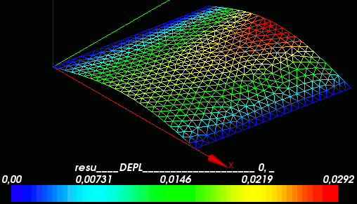
- viewing displacement in Salome
- determination of stresses
- interface ASTK
Definition of the geometry
planar shell
Geometry:
- L = 11.38 m
- Thickness = 0.55 m
Loads:
[type] [group] [value]
- Presure1 (Fbot) = 29.5e3 Pa
- Presure2 (Fmain)= 25.8e3 Pa
- Presure3 (Ftop) = 24.3e3 Pa
- Presure4 (Fcentre1,Fcentre2)= 182.6e3 Pa
Boundary conditions:
- Lbot (DX=0.0, DY=0.0, DZ=0.0)
- Ltop (DZ=0.0)
Material:
Concrete
- E = 32e9 Pa
- Nu = 0.2
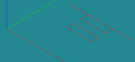
Create all points and lines using: [New Entity]->[Basic}->[Point] and [New Entity]->[Basic]->[Line]
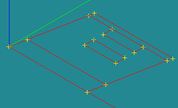 :
: 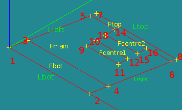
The coordinates are:
P1 = geompy.MakeVertex(  0.000,  0.00, 0.00)
P2 = geompy.MakeVertex( 11.380,  0.00, 0.00)
P3 = geompy.MakeVertex(  0.433,  2.25, 0.00)
P4 = geompy.MakeVertex( 11.813,  2.25, 0.00)
P5 = geompy.MakeVertex(  1.875,  9.75, 0.00)
P6 = geompy.MakeVertex( 13.255,  9.75, 0.00)
P7 = geompy.MakeVertex(  2.010, 10.45, 0.00)
P8 = geompy.MakeVertex( 13.390, 10.45, 0.00)
P9 = geompy.MakeVertex(  5.300,  5.72, 0.00)
P10 = geompy.MakeVertex( 5.300,  7.05, 0.00)
P11 = geompy.MakeVertex( 9.830,  5.72, 0.00)
P12 = geompy.MakeVertex( 9.830,  7.05, 0.00)
P13 = geompy.MakeVertex( 5.300,  8.42, 0.00)
P14 = geompy.MakeVertex( 5.300,  9.75, 0.00)
P15 = geompy.MakeVertex( 9.830,  8.42, 0.00)
P16 = geompy.MakeVertex( 9.830,  9.75, 0.00)
Create one big face Ftotal [New Entity]->[Build]->[Face]
Ftotal: Line7,Line6,Line8,Line12,Line11,Line10,Line9,Line1
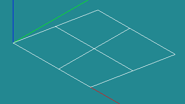
Create three wires [New Entity]->[Build]->[Wire]
- Wire1: Line3,Line4,Line5
- Wire2: Line17,Line18,Line19
- Wire3: Line13,Line14,Line15,Line16
Create vector [New Entity]->[Basic]->[Vector]
(0,0,1)
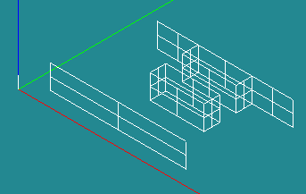
Create four extrusions [New Entity]->[Generation]->[Extrusion]
- Extrusion1: Wire1,vz
- Extrusion2: Wire2,vz
- Extrusion3: Wire3,vz
- Extrusion4: Line2,vz
Partitioning of the geometry
Why: we need groups for loads and boundary conditions. Partitioning the geometry makes sure that the for resulting mesh each group is meshed along its borders correctly and the mesh is connected between the groups
How: the geometry is divided by planes or 2D surfaces. These Tool objects need to divide the geometry completely in two seperate parts. In Salome several Tool objects can be choosen in one Partition operation. After the partitioning the groups need to be created. Int the calculation with Aster these groups can be used to define loads, boundary conditions, displacements, stresses, strains etc.
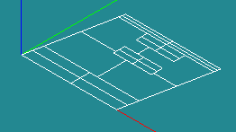
Create partition [Operations]->[Partition]
- Part_main: Ftotal,Extrusion1,Extrusion2,Extrusion3,Extrusion4
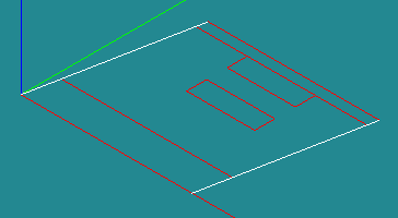
Create two groups for boundary conditions [New Entity]->[Group]->[Create]
Shape type: line
Main Shape: Part_main
- Lleft: left lines: Line7,Line8,Line9
- Lright: right lines: Line10,Line11,Line12
Meshing
how
tria -quad?
linear vs quadratic elements
Triangle mesh
Set Mesh 1D: Composite Side discretisation
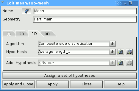
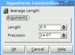
Set Mesh 1D Average lenght: 0,5
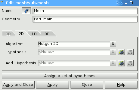
Mesh 2D settings: Netgen 2d
Mesh info:
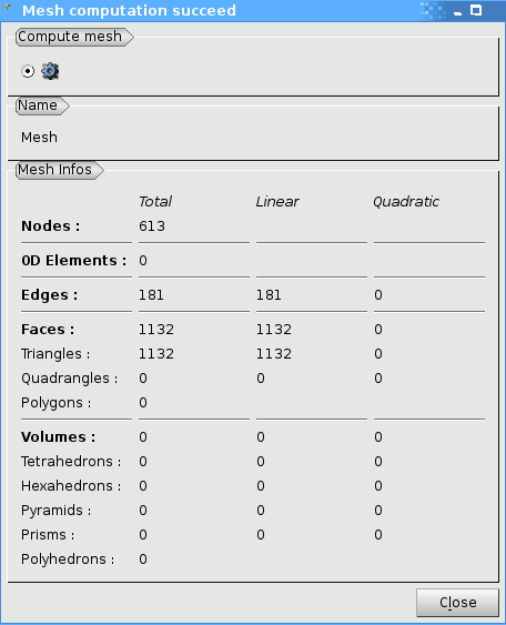
Computed Mesh:

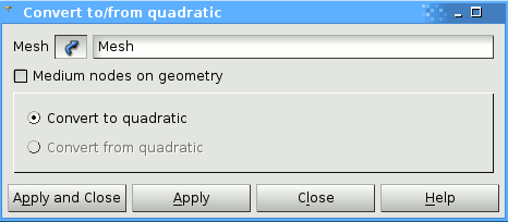
Since we are going to use COQUE_3D elements in the calculation, we need quadratic elements. So we convert the linear to quadratic mesh. If you want to make sure that the midside nodes will be locked to the geometry, you can tick the medium nodes on geometry.
Save the mesh: in the mesh module, right click on the <mesh_name> --> Export to MED file, give file name or accept default (Mesh.med in this case) and <save>. Now the mesh is available for Aster and calculations can be performed.
ASTK - Aster
For the calculations we need two input files:
- mesh file, this has been discussed in the previous part
- command file, a list of commands for processing by Aster
Several output files are generated by Aster, the most common are:
- error file, *.err
- message file, *.mess
- results mesh file, with displacements, stresses, strains of the elementsd and nodes
- base folder, for storage intermediate results
The interface between the input files, output files and Aster is called ASTK. There all the input and output files are defined. The types are defined, eg. mesh file. Whether the files will be read or written to. And the Fortran logical file number or unit number LU is defined. See for more information .....
[[1]]
Shell6.comm.zip http://www.caelinux.org/wiki/images/e/e4/Shell6.comm.zip - obsolete: bad bc

