Difference between revisions of "Contrib:KeesWouters/plate/variable pressure"
Keeswouters (Talk | contribs) m (→General way of determination of the pressure) |
Keeswouters (Talk | contribs) m (→Determination of the pressure) |
||
| (14 intermediate revisions by the same user not shown) | |||
| Line 1: | Line 1: | ||
=='''Varying pressure of shells - use of Python'''== | =='''Varying pressure of shells - use of Python'''== | ||
| − | [under construction] | + | [under construction - nearly finished] |
If you are already familiar to Code Aster, enjoy this. If you are new to Code Aster have a look [http://www.caelinux.org/wiki/index.php/Contrib:KeesWouters/platedynamics here] first please.<br/> | If you are already familiar to Code Aster, enjoy this. If you are new to Code Aster have a look [http://www.caelinux.org/wiki/index.php/Contrib:KeesWouters/platedynamics here] first please.<br/> | ||
| Line 18: | Line 18: | ||
* determine the coordinates of all the nodes and finally | * determine the coordinates of all the nodes and finally | ||
* determine the centre of gravity and | * determine the centre of gravity and | ||
| − | * generate the | + | * generate the pressure for each shell element |
by Python commands. | by Python commands. | ||
The pressure depends on the centre y-value of each shell element. It is conveinient to use the added, last node of each shell element of the connectivity list. This node has been added in the Code-Aster command file by the MODI_MAILLAGE commnand to modify the QUAD8 to QUAD9 element. | The pressure depends on the centre y-value of each shell element. It is conveinient to use the added, last node of each shell element of the connectivity list. This node has been added in the Code-Aster command file by the MODI_MAILLAGE commnand to modify the QUAD8 to QUAD9 element. | ||
| − | The geometry and mesh is shown in the picture below. The main dimensions are: [x1, x2; y1, y2; z1, z2] = [0.00,1.00; 0.00,3.00; 1.25,2.35], inclined plate in y direction. | + | The geometry and mesh is shown in the picture below. The main dimensions are: [x1, x2; y1, y2; z1, z2] = [0.00,1.00; 0.00,3.00; 1.25,2.35], inclined plate in y direction. Thickness of the shell is constant 1 [mm]. |
: [[Image:kw_variable_pressure_largemesh.png]] : [[Image:kw_variable_pressure_mesh.png]] | : [[Image:kw_variable_pressure_largemesh.png]] : [[Image:kw_variable_pressure_mesh.png]] | ||
| Line 99: | Line 99: | ||
meshCA = MAIL_PY() | meshCA = MAIL_PY() | ||
meshCA.FromAster(modiMesh) | meshCA.FromAster(modiMesh) | ||
| − | In '''meshCA''' [CodeAster mesh, derived from the read and modified mesh ''modiMesh''] all the quantities can be extracted | + | In '''meshCA''' [CodeAster mesh, derived from the read and modified mesh ''modiMesh''] all the quantities can be extracted. Note this is the function call with argument ''mesh'' instead of ''modiMesh''. |
def ApplyPressureOnGroup(mesh,groupstr,info): | def ApplyPressureOnGroup(mesh,groupstr,info): | ||
| Line 127: | Line 127: | ||
==='''Determination of the pressure'''=== | ==='''Determination of the pressure'''=== | ||
| − | The pressure on each element of the GROUP_MA='shell' is collected in a dictionary PressureOnShell. First initialise the dictionary. Then iterate over each element of the group and determine the pressure. | + | The pressure on each element of the GROUP_MA='shell' is collected in a dictionary PressureOnShell. First initialise the dictionary. Then iterate over each element of the group and determine the pressure. The nubmer of iterations is defined by the number of elements in the ElemGroup of groupstr. |
| − | The | + | |
* initialise PressureOnShell | * initialise PressureOnShell | ||
* iteratie over the elements: for ii in xrange(len(ElemGroup[groupstr])) | * iteratie over the elements: for ii in xrange(len(ElemGroup[groupstr])) | ||
| Line 145: | Line 144: | ||
CentreNode = ElemConnect[ElementNumber][-1] ### centre node coordinate stored in last ElementConnnect | CentreNode = ElemConnect[ElementNumber][-1] ### centre node coordinate stored in last ElementConnnect | ||
Centrexyz = NodeCoord[CentreNode] | Centrexyz = NodeCoord[CentreNode] | ||
| − | yCentreCoord = Centrexyz[1] # [0] xcoord [1] ycoord [2] zcoord | + | yCentreCoord = Centrexyz[1] # [0]:xcoord [1]:ycoord [2]:zcoord |
# make thickness depending on y coordinate (1) of centre node only | # make thickness depending on y coordinate (1) of centre node only | ||
| Line 159: | Line 158: | ||
=='''Results'''== | =='''Results'''== | ||
| − | |||
| − | |||
: [[Image:kw_dz_variable_pressure_mesh1.png]] : [[Image:Kw_dz_variable_pressure_12.png]]<br/> | : [[Image:kw_dz_variable_pressure_mesh1.png]] : [[Image:Kw_dz_variable_pressure_12.png]]<br/> | ||
| − | + | In the left picture the finer mesh of the shell is shown. The picture show the z deformation due to a variable pressure on the elements.<br/> | |
In the picture on the right the pressure on the shell depends on the y coordinates in two ways:<br/> | In the picture on the right the pressure on the shell depends on the y coordinates in two ways:<br/> | ||
* pressure increases in positive y direction (Pshell = 1000*yCentrecoord) and | * pressure increases in positive y direction (Pshell = 1000*yCentrecoord) and | ||
| − | * pressure increases in negative y direction (Pshell = 1000*(3.5-yCentreCoord)), note that the length of the plate in y direction is 3.5. | + | * pressure increases in negative y direction (Pshell = 1000*(3.5-yCentreCoord)), note that the length of the plate in y direction is 3.5 [m]. |
| + | |||
| + | =='''Download the files'''== | ||
| + | * [[Media:kw_variable_pressure.zip]] version CA11.3 | ||
| + | Input files (to be adapted): | ||
| + | * Python script for defining the geometry and mesh (geom_mesh_shell.py), load this file by File --> load script (cntrl T in the object browser), refresh (F5) after running. Change on line 11 the variable ''meshsize'' between 0.0 (course 3x4 mesh) and 1.0 (fine)<br/> | ||
| + | ** Save the mesh by (should be done automatic now ... via inspect module) | ||
| + | *** change to Mesh module | ||
| + | *** right clicking in the object browser by right clicking on the mesh name ''Mshell''; select ''Export to MED'' | ||
| + | *** change mesh file name to mshell.med and click ''save'' | ||
| + | * ASTK file (shellist.astk, you need to edit the path to your requirements ...). To start Code Aster calculation press ''Run''. Interactive enabled, Interactive-follow-up disabled, nodebug enabled. | ||
| + | * command file (shell_static_d.comm), change sys.path.append('.....') for next file | ||
| + | * construct_shell_thickness Python file: place this file on your system and add the Python system path in your command file | ||
| + | ** import sys #line 9 | ||
| + | ** sys.path.append('/<your_path_to_construct_shell_thickness>') | ||
| + | |||
| + | the Python file construct_shell_thickness Python file contains a functions for: | ||
| + | * applying a variable thickness to the shells | ||
| + | * applying a variable pressure on the shell elements | ||
| + | |||
That is all for now<br/> | That is all for now<br/> | ||
| − | + | kees | |
| − | kees | + | |
Latest revision as of 15:19, 26 January 2013
Contents
Varying pressure of shells - use of Python
[under construction - nearly finished]
If you are already familiar to Code Aster, enjoy this. If you are new to Code Aster have a look here first please.
A similar description for variable thickness of a plate is given in Contrib:KeesWouters/plate/thickness
november 2010 - SalomeMeca 2010 (Code Aster 10.2) - Ubuntu Meerkat 10.10 64bits.
January 2013 - update to Code Aster version 11.3 - Salome 6.6.0 - Linux Mint 14 Nadia
Static displacement of a shell under pressure
This is just a simple example of the use of shells (coque_3d) for static calculations. The main focus is on varying the pressure on a shell element by a Python list. The pressure on the shell depends on the centre y coordinate of the element. For geometry, mesh and material property details see, once again, Contrib:KeesWouters/plate/thickness.
General way of determination of the pressure
The geometry and mesh are generated in Salome in the standard way. In Code Aster the mesh is read, including nodes number, node coordinates, element types and element connectivity. We use quadratic quad8 elements that are converted to quad9 (coque_3d) elements suitable for C-Aster.
Of each element
- determine the nodes are defined by the connectivity matrix,
- determine the coordinates of all the nodes and finally
- determine the centre of gravity and
- generate the pressure for each shell element
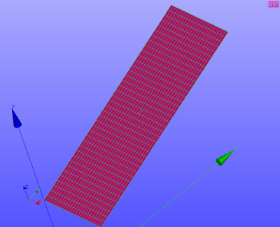
by Python commands. The pressure depends on the centre y-value of each shell element. It is conveinient to use the added, last node of each shell element of the connectivity list. This node has been added in the Code-Aster command file by the MODI_MAILLAGE commnand to modify the QUAD8 to QUAD9 element. The geometry and mesh is shown in the picture below. The main dimensions are: [x1, x2; y1, y2; z1, z2] = [0.00,1.00; 0.00,3.00; 1.25,2.35], inclined plate in y direction. Thickness of the shell is constant 1 [mm].
-
 :
: 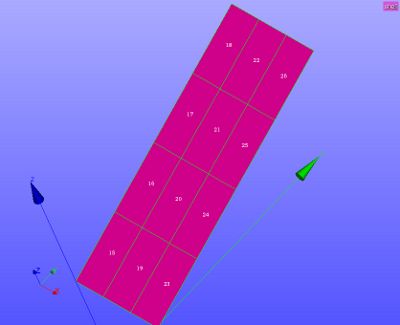


left picture with fine mesh - right picture with course 3x4 mesh
General procedure for applying pressure on shells
Among others, in Code Aster forum the procedure is discussed.
In Code Aster, after reading the initial mesh, the quad8 elements are converted to quad9 (coque_3d compatible) elements. This mesh is called modimesh (modified mesh) and is used as the basis for the further operations. Note that the last node in the connectivity list of the element is the added, centre node that will be used for applying the pressure value.
First we adapt the DEBUT() command since we need real Python commands:
DEBUT(PAR_LOT='NON');
We import the Python partition module in the command file to read mesh quantities. The Python file for determining the pressure on the shells is a Python script/module/file is ..... .
from Utilitai.partition import *
import sys
sys.path.append('/cae/caexample/shell/shellplate_thlist')   ## define your own path here
from construct_shell_thickness import *
# reading the initial mesh meshinit with quad8 elements
meshinit=LIRE_MAILLAGE(FORMAT='MED',INFO=1,);
# and converting it to quad9, coque_3d elements
modimesh=CREA_MAILLAGE(MAILLAGE=initmesh,
                     MODI_MAILLE=(_F(TOUT='OUI',OPTION='QUAD8_9',),),);
info  = 0
PressureOnShell = ApplyPressureOnGroup(modiMesh,'shell',info)
ApplyPr = AFFE_CHAR_MECA(MODELE=cocModel,FORCE_COQUE=PressureOnShell);
Details for applying pressure on shells
The Python function
- PressureOnShell = ApplyPressureOnGroup(mesh,groupstr,info) does the work.
Three arguments for the function need to be given now:
- mesh: the mesh,
- groupstr: the group where the pressure needs to be applied and
- info for controlling printed information: ## 0:1:2 - print additional information 0:none 1:general 2:detailed information
(Note that the group groupstr has been added compared to the function for determining the thickness. This need to be adapted there also.)
We have a look at this in detail. Standard, applying the load, in this case the pressure on a shell is performed by the command AFFE_CHAR_MECA:
- ApplyPr = AFFE_CHAR_MECA(MODELE=cocModel,FORCE_COQUE=_F(GROUP_MA='shell',PRES=pressure,),);
Now remember that the parameters in the _F(...) operator can be replaced by a Python dictionary, in this case: ellist = {'GROUP_MA': 'shell','PRESS':1e5} or more general:
ellist = [{'MAILLE': 'Mxxx','PRESS':Pxxx},
          {'MAILLE': 'Myyy','PRESS':Pyyy},
            .......
            .......
          {'MAILLE': 'Mzzz','PRESS':Pzzz}]
where 'Mxxx' is the element number and Pxxx is the corresponding element pressure. Replace AFFE_CHAR_MECA(...) by:
- ApplyPr = AFFE_CHAR_MECA(MODELE=cocModel,FORCE_COQUE=PressureOnShell)
where the dictionary PressureOnShell has been filled by the Python function:
PressureOnShell = ApplyPressureOnGroup(modiMesh,'shell',info)
where 'Mxxx' is the element number and Pxxx is the corresponding element pressure. For the 3x4 mesh the dictionary ApplyPressureShell generated by ApplyPressureOnGroup(...) is as follows:
PressureOnShell =
 [{'MAILLE': 'M15', 'PRES':  312.5},
  {'MAILLE': 'M16', 'PRES':  937.5},
  {'MAILLE': 'M17', 'PRES': 1562.5},
  {'MAILLE': 'M18', 'PRES': 2187.5},
  {'MAILLE': 'M19', 'PRES':  312.5},
  {'MAILLE': 'M20', 'PRES':  937.5},
  {'MAILLE': 'M21', 'PRES': 1562.5},
  {'MAILLE': 'M22', 'PRES': 2187.5},
  {'MAILLE': 'M23', 'PRES':  312.5},
  {'MAILLE': 'M24', 'PRES':  937.5},
  {'MAILLE': 'M25', 'PRES': 1562.5},
  {'MAILLE': 'M26', 'PRES': 2187.5}]
Note that the pressure depends on the centre y coordinate as follows: Pshell = yCentreCoord*1000. Of course, you can -and should- define your own dependency here.
Extraction of coordinates
In this example, the actual thickness of the shell depends on the y coordinate at the centre of the element. This is extracted as follows: first read the mesh and extract the mesh by the commands:
meshCA   = MAIL_PY()
meshCA.FromAster(modiMesh)
In meshCA [CodeAster mesh, derived from the read and modified mesh modiMesh] all the quantities can be extracted. Note this is the function call with argument mesh instead of modiMesh.
def ApplyPressureOnGroup(mesh,groupstr,info):
  PyMesh   = MAIL_PY()         # convert CodeAster mesh to Python
  PyMesh.FromAster(mesh);
  nonu     = PyMesh.dime_maillage[0]   ## number of nodes
  elnu     = PyMesh.dime_maillage[2]   ## number of elements
  NodeCoord    = PyMesh.cn             ## xyz coordinates of nodes (nonu*3 matrix)
  ElemConnect  = PyMesh.co             ## node numbers of elements (elnu*x matrix)
  NodeList = list(PyMesh.correspondance_noeuds)
  ElemList = list(PyMesh.correspondance_mailles)
  ElemType = list(PyMesh.tm)
  NodeGroup = PyMesh.gno               ## list of GROUP_NO groups
  ElemGroup = PyMesh.gma               ## list of GROUP_MA groups, eg groupstr
  ....
The procedure is then as follows:
- initialise the dictionary
- step through element list of the group GROUP_MA='shell'
- read connectivity of the element, ie all attached node numbers: connectivity = meshCA.co
- step through all node of the element, in case of QUAD9 -correct- 9 nodes
- determine nodes and its coordinates
- compute average (y) coordinate or select last, centre node element
- define pressure on the shell depending on centre y coordinate
- add the pressure and element to dictionary {...}
Determination of the pressure
The pressure on each element of the GROUP_MA='shell' is collected in a dictionary PressureOnShell. First initialise the dictionary. Then iterate over each element of the group and determine the pressure. The nubmer of iterations is defined by the number of elements in the ElemGroup of groupstr.
- initialise PressureOnShell
- iteratie over the elements: for ii in xrange(len(ElemGroup[groupstr]))
- ElementNumber is the retrieved from ElemGroup[groupstr][ii] and the
- CentreNode is the last node (index -1) of the ElemConnect array
- Centrexyz contains the x, y and z coordinates of CentreNode
- yCentreCoord is the second index (Python index 1) of Centrexyz and finally the
- temppress is the desired pressure depending on the y coordinate of the centre node
In real Python code:
  ...
  PressureOnShell=[]                   ## initialise PressureOnShell dictionary
  for ii in xrange(len(ElemGroup[groupstr])):
     ElementNumber = ElemGroup[groupstr][ii]
     ### use centre node (last node) of element (tested for quad9 only, should work for tria7 aswell):
     CentreNode = ElemConnect[ElementNumber][-1]       ### centre node coordinate stored in last ElementConnnect
     Centrexyz = NodeCoord[CentreNode]
     yCentreCoord = Centrexyz[1]    # [0]:xcoord [1]:ycoord [2]:zcoord
     # make thickness depending on y coordinate (1) of centre node only
     # define your own code here
     #temppress = (2.5-yCentreCoord)*1000
     temppress = yCentreCoord*1000
     ## add 1 for element number Mxx (conversion from PyMesh to CAmesh)
     PressureOnShell.append({'PRES':temppress,'MAILLE':'M%d'%(ElementNumber+1)});
     #FORCE_COQUE=_F(GROUP_MA='shell',PRES=pressure,)) equivalent to
     #FORCE_COQUE=_F(PressureOnShell))
  return PressureOnShell
Results
-
 :
: 


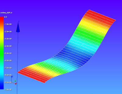
In the left picture the finer mesh of the shell is shown. The picture show the z deformation due to a variable pressure on the elements.
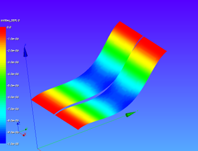
In the picture on the right the pressure on the shell depends on the y coordinates in two ways:
- pressure increases in positive y direction (Pshell = 1000*yCentrecoord) and
- pressure increases in negative y direction (Pshell = 1000*(3.5-yCentreCoord)), note that the length of the plate in y direction is 3.5 [m].
Download the files
- Media:kw_variable_pressure.zip version CA11.3
Input files (to be adapted):
- Python script for defining the geometry and mesh (geom_mesh_shell.py), load this file by File --> load script (cntrl T in the object browser), refresh (F5) after running. Change on line 11 the variable meshsize between 0.0 (course 3x4 mesh) and 1.0 (fine)
- Save the mesh by (should be done automatic now ... via inspect module)
- change to Mesh module
- right clicking in the object browser by right clicking on the mesh name Mshell; select Export to MED
- change mesh file name to mshell.med and click save
- Save the mesh by (should be done automatic now ... via inspect module)
- ASTK file (shellist.astk, you need to edit the path to your requirements ...). To start Code Aster calculation press Run. Interactive enabled, Interactive-follow-up disabled, nodebug enabled.
- command file (shell_static_d.comm), change sys.path.append('.....') for next file
- construct_shell_thickness Python file: place this file on your system and add the Python system path in your command file
- import sys #line 9
- sys.path.append('/<your_path_to_construct_shell_thickness>')
the Python file construct_shell_thickness Python file contains a functions for:
- applying a variable thickness to the shells
- applying a variable pressure on the shell elements
That is all for now
kees