Contrib:KeesWouters/plate/thickness
Contents
Varying thickness of shells - by Python
If you are already familiar to Code Aster, enjoy this. If you are new to Code Aster have a look here first please.
Static displacement of a shell under pressure
november 2010 - SalomeMeca 2010 (Code Aster 10.2) - Ubuntu Meerkat 10.10 64bits.
This is just a simple example of the use of shells (coque_3d) for static calculations. The main focus is on varying thickness of the shell by a Python list. The thickness of the shell depends on the average Ycog coordinate of the shell element.
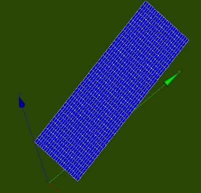
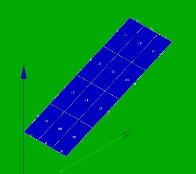
Two meshes are used throughout this contribution: a course mesh (3 by 4 elements) and a fine mesh. In the geometry and mesh file (download as at the end) the meshsize can be set by the variable meshsize (number between 0.0 and 1.0). The course mesh I have been using for experimenting. The fine mesh to show more reasonable results.
General way of determination of the shell thickness
First the geometry and mesh is generated in Salome in the standard way. In Code Aster the mesh is read, including nodes number, node coordinates, element types and element connectivity. We use quadratic quad8 elements that are converted to quad9 (coque_3d) elements suitable for C Aster. Of each element the nodes are determined by the connectivity matrix, the coordinates of all the nodes and finally the centre of gravity. This includes the y coordinate Ycog. The element thickness th is calculated by th = Ycog*0.1+0.01 and stored in a Python list. This list is passed to the AFFE_CARA_ELEM command. Further processing C Aster is from then on as usual.
Geometry, mesh and material properties
The construction is a rectangle in the xyz plane. Minimum x is 0, maximum x is 1.0 [m]. For y and z these values are: [ymin, ymax] = [0.0, 2.5] and [zmin, zmax] = [1.25, 2.3456]. The varying thickness of the plate depends on the average y coordinate as follows: th = Ycog*0.1+0.01.
Boundary conditions are as follows: the two edges parallel to the y axis are restricted in all six directions. The material is steel, its mechanical properties are defined by the following parameters: Young's modulus E = 2.1e11 Pa, poisson ratio nu=0.28 [-] and density -though not needed- here rho=7850 kg/m3. For more details see e.g. here where the details of the general calculation procedure are given. In the next part we concentrate on the extraction of the coordinates of the elements and the definition of the thickness of each element.
Extraction of the coordinates
Among others, in this Code Aster forum this procedure is discussed.
In Code Aster, after reading the initial mesh, the quad8 elements are converted to quad9 (coque_3d compatible) elements. This mesh is called meshmod (modified mesh) and is used as the basis for the further operations.
First we adapt the DEBUT() command since we need real Python commands:
DEBUT(PAR_LOT='NON');
We import the partition module in the command file to read mesh quantities. And the complete definition of the thickness of the shells is stored in a separate Python script/module/file (construct_shell_thickness) in the path defined below:
from Utilitai.partition import *
import sys
sys.path.append('/cae/caexample/shell/shellplate_thlist')
from construct_shell_thickness import *
After reading the initial mesh meshinit with quad8 elements
meshinit=LIRE_MAILLAGE(FORMAT='MED',INFO=1,);
and converting it to quad9, coque_3d elements
meshmod=CREA_MAILLAGE(MAILLAGE=meshinit,
                     MODI_MAILLE=(_F(TOUT='OUI',
                                     OPTION='QUAD8_9',),),);
we define the thickness of each element by calling
info = 1   ## true/false - print additional information
ThicknessGroupShell = construct_shell_thickness(meshmod,info)
The Python script construct_shell_thickness does the whole work.
We have a look at this in detail. Standard, the characteristics of the shell are defined by the AFFE_CARA_ELEM command with, among others, the following parameters:
shellch=AFFE_CARA_ELEM(MODELE=modmod,
                      COQUE=_F(GROUP_MA='shell',
                               EPAIS=0.001,),);
Now remember that the parameters in the _F(...) operator can be replaced by a Python list, in this case: ellist = {'GROUP_MA': 'shell','EPAIS':0.001}. Or more general:
 ellist = [{'MAILLE': 'Mxxx','EPAIS':thxxx},
           {'MAILLE': 'Myyy','EPAIS':thyyy},
             .......
             .......
           {'MAILLE': 'Mzzz','EPAIS':thzzz}]
where 'Mxxx' is the element number and thxxx is the corresponding element thickness. Eg in this example the following list thicknessGroupShell is generated:
 [{'EPAIS': 0.16625000000000001, 'MAILLE': 'M15'},
 {'EPAIS': 0.22875000000000001, 'MAILLE': 'M16'},
   ....
   ....
 {'EPAIS': 0.22875000000000001, 'MAILLE': 'M25'},
 {'EPAIS': 0.10375, 'MAILLE': 'M26'}]
General - extraction of coordinates
The actual thickness of the shell depends on the average y coordinate of it. This is extracted as follows. First read the mesh and extract a new mesh by the commands
meshCA   = MAIL_PY()
meshCA.FromAster(mesh)
In meshCA all the quantities can be extracted:
 nonu     = meshCA.dime_maillage[0]    ## number of nodes
 elnu     = meshCA.dime_maillage[2]    ## number of elements
 ncoord   = meshCA.cn                  ## coordinates of the nodes
 connect  = meshCA.co                  ## connectivity of the element
 NodeList = list(meshCA.correspondance_noeuds)   ## says it all
 ElemList = list(meshCA.correspondance_mailles)
 ElemType = list(meshCA.tm)
The procedure is then as follows:
- step through element list
- check if element type is quad9/coque_3d/number 16
- read connectivity of the element: connectivity = meshCA.co
- step through all node of the element
- determine nodes and its coordinates
- compute average (y) coordinate
- define thickness depending on (y) coordinate
- add thickness and element to list {...}
In 'real' Python code:
for ii in xrange(len(ElemList)):
  print ElemType[ii]
  if ElemType[ii]==16:  # select shell (coque_3d) elements
    #print connect[ii]
    shellcount +=1
ThicknessGroupShell=[]
thickness = [None]*shellcount
shellcount = 0
for ii in xrange(len(ElemList)):
  print 'elementtype: ',ii,ElemType[ii]
  if ElemType[ii]==16:  # select shell coque_3d elements 14:quad8, 16:quad9
    sumxyz = [0.0, 0.0, 0.0]
    ncount = len(connect[ii])    # should be 9 for coque_3d (elementType 16)
    for jj in xrange(0,ncount):
      Gnode = connect[ii][jj]    # globalnode = connect[elemii,internal_nodejj]
      sumxyz += ncoord[Gnode]    # this might be written more compact --> for later
    sumxyz /=ncount
    # define your own code for thickness here
    # thickness now depends on average y coordinate only
    thickness[shellcount] = sumxyz[1]*0.1+0.01  # make thickness depent on y coordinate
    tempth = thickness[shellcount]
    shellcount +=1
    #print 'average xyz - centre point: ',sumxyz,ncoord[Gnode]  #centre point is same average nodes
    ThicknessGroupShell.append({'EPAIS':tempth,'MAILLE':'M%d'%(ii+1)});  ## add 1 for element number Mxx
Normally, vecteur or angle??? and NCOU ??? need to be defined as well.
Things that might go wrong
Of course, nothing will ever go wrong. Except code written in Python and used in conjunction with Code Aster of course. All things go wrong then. First all kind of syntax error occur. These are relatively easy to capture and remove, because Python normally offers help by issuing nice error messages. Things are less trivial if you forget the +1 to inidicate the mesh element in the append command: 'MAILLE':'M%d'%(ii+1) because of the different numbering of Salome and Code Aster mesh (I guess). To see how the mesh is built up you can print the whole mesh FromAster:
meshCA = MAIL_PY()
meshCA.FromAster(mesh)
print meshCA,
Then you get eg:
COOR_3D
N1         1.00000000000000E+00   2.50000000000000E+00   2.34560000000000E+00
....
SEG3
M1        N3       N17      N18
....
QUAD9
M15       N10    N29    N30    N12    N36    N37    N38     N13    NS1
M16       N7     N5     N32    N29    N8     N42    N43     N35    NS2
....
GROUP_MA
Linex0
M5       M7       M10      M11
FINSF
%
GROUP_MA
Linex1
M3       M9       M12      M14
FINSF
%
GROUP_MA
shell
M15      M16      M17      M18      M19      M20      M21      M22
M23      M24      M25      M26
This allows you to check the correct node numbers, elements, connectivity and groups defined in your mesh. Starting with a small mesh is advicable.
Also carefully check the code that generates the thickness of the shell. It is very easy to make a mistake: selecting the wrong index of the coordinate array is an obvious one.
For a small mesh (3 by 4 elements) the Python list is as follows:
thicknessGroupShell:
[{'EPAIS': 0.16625000000000001, 'MAILLE': 'M15'},
 {'EPAIS': 0.22875000000000001, 'MAILLE': 'M16'},
 {'EPAIS': 0.041250000000000002, 'MAILLE': 'M17'},
 {'EPAIS': 0.22875000000000001, 'MAILLE': 'M18'},
 {'EPAIS': 0.16625000000000001, 'MAILLE': 'M19'},
 {'EPAIS': 0.10375, 'MAILLE': 'M20'},
 {'EPAIS': 0.10375, 'MAILLE': 'M21'},
 {'EPAIS': 0.041250000000000002, 'MAILLE': 'M22'},
 {'EPAIS': 0.041250000000000002, 'MAILLE': 'M23'},
 {'EPAIS': 0.16625000000000001, 'MAILLE': 'M24'},
 {'EPAIS': 0.22875000000000001, 'MAILLE': 'M25'},
 {'EPAIS': 0.10375, 'MAILLE': 'M26'}]
Remarks
Note that you could select the midplane node NSxxx just as well to make the thickness dependending on (NSxxx is added to the quad8 element by the modi_maillage command). Then no need to compute the average values of the coordinates of the 8 nodes on the egde.
Continue with the commands
Now we follow the standard procedure for calculating the static displacement of the shell under pressure. Normally we define the the thickness of the shell by:
th = 0.02
shellch=AFFE_CARA_ELEM(MODELE=modelc,
                      COQUE=_F(GROUP_MA='shell',
                               EPAIS=th,),);
                               #ANGL_REP=(0.1,0.3,),
                               #COQUE_NCOU=1,),);
what will be replaced by:
shellch=AFFE_CARA_ELEM(MODELE=modelc,COQUE=(ThicknessGroupShell),);
Very compact, I would say. Unfortunately the whole process defined in construct_shell_thickness hides the effort. The MECA_STATIQUE command carries out the computation.
result=MECA_STATIQUE(MODELE=modelc,
                    CHAM_MATER=material,
                    CARA_ELEM=shellch,
                    EXCIT=_F(CHARGE=clamped,),);
where of course the model modelc, the material properties, the shell characteristics shellch (oeps) and the charge clamped -being boundary conditions in this case- have been defined in advance. After calculating the element results and printing the results by
result = CALC_ELEM(...) and
IMPR_RESU(...)
we can display the results in Salome (or any other post processing program).
Results
Clearly the solution is asymmetric due to the increasing thickness and hence stiffness of the shells in y direction.
Input files - download
References
From Code Aster references:
[u2.02.01] Notice d’utilisation des éléments plaques, coques et coques volumiques SHB
[u4.81.22] Opérateur POST_ELEM
[u5.02.00] Manuel d’Utilisation - Fascicule U5.0- : Structure de données resultat Document: U5.02.00 - Présentation des tables
[u3.12.03] Modélisation COQUE_3D
[R3.07.04] Eléments finis de coques volumiques
[R3.07.05] Éléments de coques volumiques en non linéaire
géométrique
Code Aster forum - discussion: [Code Aster forum]
--keeswouters november 2010


