Difference between revisions of "Contrib:KeesWouters/plate/thickness"
Keeswouters (Talk | contribs) m (→'''Using coque_3d shell elements''') |
Keeswouters (Talk | contribs) m (→General - extraction of coordinates) |
||
| (126 intermediate revisions by the same user not shown) | |||
| Line 1: | Line 1: | ||
=='''Varying thickness of shells - by Python'''== | =='''Varying thickness of shells - by Python'''== | ||
| − | + | If you are already familiar to Code Aster, enjoy this. If you are new to Code Aster have a look [http://www.caelinux.org/wiki/index.php/Contrib:KeesWouters/platedynamics here] first please.<br/> | |
| − | + | ||
november 2010 - SalomeMeca 2010 (Code Aster 10.2) - Ubuntu Meerkat 10.10 64bits. | november 2010 - SalomeMeca 2010 (Code Aster 10.2) - Ubuntu Meerkat 10.10 64bits. | ||
| + | <br/> | ||
| + | January 2013 - update to Code Aster version 11.3 - Salome 6.6.0 - Linux Mint 14 Nadia<br/> | ||
| + | For a similar contribution with variable pressue see: [[Contrib:KeesWouters/plate/variable_pressure]] | ||
| + | |||
| + | ==='''Static displacement of a shell under pressure'''=== | ||
This is just a simple example of the use of shells (coque_3d) for static calculations. The main focus is on varying thickness of the shell by a Python list. The thickness of the shell depends on the average Ycog coordinate of the shell element. | This is just a simple example of the use of shells (coque_3d) for static calculations. The main focus is on varying thickness of the shell by a Python list. The thickness of the shell depends on the average Ycog coordinate of the shell element. | ||
| + | Two meshes are used throughout this contribution: a course mesh (3 by 4 elements) and a fine mesh. In the geometry and mesh file (download as at the end) the meshsize can be set by the variable ''meshsize'' (number between 0.0 and 1.0). The course mesh I have been using for experimenting. The fine mesh to show more reasonable results. | ||
==='''General way of determination of the shell thickness'''=== | ==='''General way of determination of the shell thickness'''=== | ||
| − | + | The geometry and mesh are generated in Salome in the standard way. In Code Aster the mesh is read, including nodes number, node coordinates, element types and element connectivity. We use quadratic quad8 elements that are converted to quad9 (coque_3d) elements suitable for C-Aster.<br/> | |
| − | + | Of each element | |
| + | * determine the nodes are defined by the connectivity matrix, | ||
| + | * determine the coordinates of all the nodes and finally | ||
| + | * determine the centre of gravity and | ||
| + | * generate the thickness of the shell | ||
| + | by Python commands. | ||
| + | This includes the y coordinate Ycog. The element thickness th is calculated by th = Ycog*0.1+0.01 and stored in a Python list. This list is passed to the AFFE_CARA_ELEM command. Further processing C-Aster is from then on as usual. | ||
==='''Geometry, mesh and material properties'''=== | ==='''Geometry, mesh and material properties'''=== | ||
| − | The construction is a rectangle in the xyz plane. | + | The construction is a rectangle in the xyz plane. The minimum and maximum x, y and z values are: |
| − | + | * x: [xmin, xmax] = [0.00, 1.00] | |
| + | * y: [ymin, ymax] = [0.00, 2.50] | ||
| + | * z: [zmin, zmax] = [1.25, 2.35] | ||
| + | The thickness of the plate we make dependent on the y coordinate of the centre of the element as follows: th = Ycog*0.1+0.01 (edit this for your own definition here of course).<br/> | ||
| + | The boundary conditions are as follows: the two edges parallel to the y axis are restricted in all six directions. The material is steel, its mechanical properties are defined by the following parameters: Young's modulus E = 2.1e11 [Pa], poisson ratio nu = 0.28 [-] and density -though not needed- here rho = 7850 [kg/m3]. For more details of the general calculation procedure see e.g. [http://www.caelinux.org/wiki/index.php/Contrib:KeesWouters/platedynamics here.] In the next part we concentrate on the extraction of the coordinates of the elements and the definition of the thickness of each element. | ||
| − | + | : [[Image:kw_varshell_geom.jpg]] | |
| − | + | =='''Extraction of the coordinates'''== | |
| − | + | Among others, in [http://www.code-aster.org/forum2/viewtopic.php?id=13692 Code Aster forum] the procedure is discussed.<br/> | |
| − | + | In Code Aster, after reading the initial mesh, the quad8 elements are converted to quad9 (coque_3d compatible) elements. This mesh is called meshmod (''modified mesh'') and is used as the basis for the further operations. | |
| − | + | ||
| − | + | ||
| − | + | First we adapt the DEBUT() command since we need ''real'' Python commands: | |
| − | + | DEBUT(PAR_LOT='NON'); | |
| − | * | + | We import the Python '''partition''' module in the command file to read mesh quantities. The definition of the thickness of the shells is stored in a separate Python script/module/file (construct_shell_thickness) in the path defined below (change for your own needs [sys.path.append('/your/path/shellplate_thlist')]): |
| − | + | from Utilitai.partition import * | |
| − | * | + | import sys |
| + | sys.path.append('/cae/caexample/shell/shellplate_thlist') | ||
| + | from construct_shell_thickness import * | ||
| − | + | After reading the initial mesh '''meshinit''' with quad8 elements | |
| − | + | meshinit=LIRE_MAILLAGE(FORMAT='MED',INFO=1,); | |
| + | and converting it to quad9, coque_3d elements | ||
| + | meshmod=CREA_MAILLAGE(MAILLAGE=meshinit, | ||
| + | MODI_MAILLE=(_F(TOUT='OUI', | ||
| + | OPTION='QUAD8_9',),),); | ||
| − | + | we define the thickness of each element by calling | |
| − | + | info = 1 ## true/false - print additional information | |
| − | + | ThicknessGroupShell = construct_shell_thickness(meshmod,info) | |
| − | + | ||
| − | + | ||
| − | + | ||
| − | + | ||
| − | + | ||
| − | + | ||
| − | + | The Python script '''construct_shell_thickness''' does the work.<br/> | |
| − | We | + | We have a look at this in detail. Standard, the characteristics of the shell are defined by the AFFE_CARA_ELEM command with, among others, the thickness parameter EPAIS: |
| − | + | shellch=AFFE_CARA_ELEM(MODELE=modmod, | |
| − | + | COQUE=_F(GROUP_MA='shell', | |
| − | + | EPAIS=0.001,),); | |
| − | + | ||
| − | + | Now remember that the parameters in the _F(...) operator can be replaced by a Python list, in this case: ellist = {'GROUP_MA': 'shell','EPAIS':0.001}. Or more general: | |
| − | + | ellist = [{'MAILLE': 'Mxxx','EPAIS':thxxx}, | |
| − | + | {'MAILLE': 'Myyy','EPAIS':thyyy}, | |
| + | :::: | ||
| + | {'MAILLE': 'Mzzz','EPAIS':thzzz}] | ||
| − | + | where 'Mxxx' is the element number and thxxx is the corresponding element thickness. Eg in this example the following list ''thicknessGroupShell'' is generated: | |
| + | [{'EPAIS': 0.16625, 'MAILLE': 'M15'}, | ||
| + | {'EPAIS': 0.22875, 'MAILLE': 'M16'}, | ||
| + | :::: | ||
| + | {'EPAIS': 0.22875, 'MAILLE': 'M25'}, | ||
| + | {'EPAIS': 0.10375, 'MAILLE': 'M26'}] | ||
| − | + | ==='''General - extraction of coordinates'''=== | |
| − | + | In this example, the actual thickness of the shell depends on the y coordinate at the centre of the element. This is extracted as follows. First read the mesh: | |
| − | + | meshCA = MAIL_PY() | |
| − | + | meshCA.FromAster(mesh) | |
| − | + | In '''meshCA''' the available mesh quantities can be extracted (nodes, elements, connectivity, coordinates): | |
| − | + | nonu = meshCA.dime_maillage[0] ## number of nodes | |
| + | elnu = meshCA.dime_maillage[2] ## number of elements | ||
| + | ncoord = meshCA.cn ## coordinates of the nodes | ||
| + | connect = meshCA.co ## connectivity of the element | ||
| + | NodeList = list(meshCA.correspondance_noeuds) ## says it all | ||
| + | ElemList = list(meshCA.correspondance_mailles) | ||
| + | ElemType = list(meshCA.tm) | ||
| − | + | The procedure is then as follows: | |
| + | * step through element list | ||
| + | ** check if element type is quad9/coque_3d/number 16 | ||
| + | ** read connectivity of the element, ie all attached node numbers: connectivity = meshCA.co | ||
| + | ** step through all node of the element | ||
| + | *** determine nodes and its coordinates | ||
| + | *** compute average (y) coordinate | ||
| + | *** define thickness depending on (y) coordinate | ||
| + | *** add thickness and element to list {...} | ||
| − | + | In 'real' Python code: | |
| + | for ii in xrange(len(ElemList)): | ||
| + | print ElemType[ii] | ||
| + | if ElemType[ii]==16: # select shell (coque_3d) elements | ||
| + | #print connect[ii] | ||
| + | shellcount +=1 | ||
| − | == | + | ThicknessGroupShell=[] # initialise variables |
| − | + | thickness = [None]*shellcount | |
| − | + | shellcount = 0 # reset shellcount | |
| + | for ii in xrange(len(ElemList)): | ||
| + | print 'elementtype: ',ii,ElemType[ii] | ||
| + | if ElemType[ii]==16: # select shell elements coque_3d (14:quad8 but only 16:quad9 available) | ||
| + | sumxyz = [0.0, 0.0, 0.0] | ||
| + | ncount = len(connect[ii]) # should be 7 for tria7 and/or 9 quad9 for coque_3d (elementType 16) | ||
| + | for jj in xrange(0,ncount): | ||
| + | Gnode = connect[ii][jj] # globalnode = connect[elemii,internal_nodejj] | ||
| + | sumxyz += ncoord[Gnode] # this might be written more compact --> for later | ||
| − | ==''' | + | sumxyz /=ncount |
| + | # define your own code for thickness here | ||
| + | # thickness now depends on average y coordinate only | ||
| + | thickness[shellcount] = sumxyz[1]*0.01+0.1 # make thickness dependending on y coordinate | ||
| + | tempth = thickness[shellcount] | ||
| + | shellcount +=1 | ||
| + | #print 'average xyz - centre point: ',sumxyz,ncoord[Gnode] #centre point is same average nodes | ||
| + | ThicknessGroupShell.append({'EPAIS':tempth,'MAILLE':'M%d'%(ii+1)}); ## add 1 for element number Mxx | ||
| − | + | If needed, vecteur, angle or NCOU can be defined as well. | |
| − | + | ==='''Things that might go wrong'''=== | |
| − | + | Of course, nothing will ever go wrong. Except code written in Python and used in conjunction with Code Aster. Then things definitely will go wrong. At least the first time by a unstructered programmer (like me?). | |
| − | + | First all kind of syntax errors occur. These are relatively easy to address and remove, because Python offers help by issuing nice error messages. Things are less trivial if you forget the +1 to inidicate the mesh element in the append command: ''' 'MAILLE':'M%d'%(ii+1)''' because of the 1 offset numbering of Salome to Code Aster mesh. To see how the mesh is built up you can print the whole mesh FromAster:<br/> | |
| − | + | meshCA = MAIL_PY() | |
| − | + | meshCA.FromAster(mesh) | |
| − | + | print meshCA, | |
| − | + | ||
| − | + | ||
| − | + | ||
| − | + | Then you get eg: | |
| − | + | COOR_3D | |
| − | + | N1 1.00000000000000E+00 2.50000000000000E+00 2.34560000000000E+00 | |
| − | + | .... | |
| − | + | SEG3 | |
| − | + | M1 N3 N17 N18 | |
| − | + | ||
| − | + | ||
| − | + | ||
| − | + | ||
| − | + | ||
| − | + | ||
| − | + | ||
| − | + | ||
| − | + | ||
| − | + | ||
| − | + | ||
| − | + | ||
| − | + | ||
| − | + | ||
| − | + | ||
| − | + | ||
| − | + | ||
| − | + | ||
| − | + | ||
| − | + | ||
| − | + | ||
| − | + | ||
| − | + | ||
| − | + | ||
| − | + | ||
| − | + | ||
| − | + | ||
| − | + | ||
| − | + | ||
| − | + | ||
| − | + | ||
| − | + | ||
| − | + | ||
| − | + | ||
| − | + | ||
| − | + | ||
.... | .... | ||
| − | + | QUAD9 | |
| + | M15 N10 N29 N30 N12 N36 N37 N38 N13 NS1 | ||
| + | M16 N7 N5 N32 N29 N8 N42 N43 N35 NS2 | ||
.... | .... | ||
| − | + | GROUP_MA | |
| + | Linex0 | ||
| + | M5 M7 M10 M11 | ||
| + | FINSF | ||
| + | % | ||
| + | GROUP_MA | ||
| + | Linex1 | ||
| + | M3 M9 M12 M14 | ||
| + | FINSF | ||
| + | % | ||
| + | GROUP_MA | ||
| + | shell | ||
| + | M15 M16 M17 M18 M19 M20 M21 M22 | ||
| + | M23 M24 M25 M26 | ||
| − | + | This allows you to check the correct node numbers, elements, connectivity and groups defined in your mesh. Starting with a small mesh is advicable.<br/> | |
| − | + | Also carefully check the code that generates the thickness of the shell. It is very easy to make a mistake: selecting the wrong index of the coordinate array is an obvious one.<br/> | |
| − | + | For a small mesh (3 by 4 elements) the Python list is as follows: | |
| − | + | ||
| − | + | thicknessGroupShell: | |
| − | + | [{'EPAIS': 0.16625, 'MAILLE': 'M15'}, | |
| − | + | {'EPAIS': 0.22875, 'MAILLE': 'M16'}, | |
| − | + | {'EPAIS': 0.04125, 'MAILLE': 'M17'}, | |
| + | {'EPAIS': 0.22875, 'MAILLE': 'M18'}, | ||
| + | {'EPAIS': 0.16625, 'MAILLE': 'M19'}, | ||
| + | {'EPAIS': 0.10375, 'MAILLE': 'M20'}, | ||
| + | {'EPAIS': 0.10375, 'MAILLE': 'M21'}, | ||
| + | {'EPAIS': 0.04125, 'MAILLE': 'M22'}, | ||
| + | {'EPAIS': 0.04125, 'MAILLE': 'M23'}, | ||
| + | {'EPAIS': 0.16625, 'MAILLE': 'M24'}, | ||
| + | {'EPAIS': 0.22875, 'MAILLE': 'M25'}, | ||
| + | {'EPAIS': 0.10375, 'MAILLE': 'M26'}] | ||
| − | |||
| − | |||
| − | |||
| − | |||
| − | |||
| − | |||
| − | |||
| − | + | '''Remarks'''<br/> | |
| − | + | Note that you could select the midplane node '''NSxxx''' just as well to make the thickness dependending on (NSxxx is added to the quad8 element by the modi_maillage command). Then there is no need to compute the average values of the coordinates of the 8 nodes on the egde. | |
| − | + | ||
| − | + | ||
| − | + | ||
| − | |||
| − | |||
| − | |||
| − | |||
| − | |||
| − | |||
| − | |||
| − | |||
| − | |||
| − | |||
| − | |||
| − | |||
| − | |||
| − | + | : [[Image:kw_varshell_3x4.jpg]] | |
| − | + | ||
| + | =='''Continue with the commands'''== | ||
| + | Now we follow the standard procedure for calculating the static displacement of the shell under pressure. Normally we define the the thickness of the shell by: | ||
| − | + | th = 0.02 | |
| − | + | shellch=AFFE_CARA_ELEM(MODELE=modelc, | |
| + | COQUE=_F(GROUP_MA='shell', | ||
| + | EPAIS=th,),); | ||
| + | #VECTEUR=(1.0,0.0,0.0,), | ||
| + | #COQUE_NCOU=1,),); | ||
| − | + | This will be replaced by: | |
| − | + | shellch=AFFE_CARA_ELEM(MODELE=modelc,COQUE=(ThicknessGroupShell),); | |
| − | + | Very compact, I would say. Unfortunately the whole process defined in '''construct_shell_thickness''' hides the effort. The MECA_STATIQUE command carries out the static analysis: | |
| − | + | result=MECA_STATIQUE(MODELE=modelc, | |
| − | + | CHAM_MATER=material, | |
| − | + | CARA_ELEM=shellch, | |
| − | + | EXCIT=_F(CHARGE=clamped,),); | |
| − | + | ||
| − | + | ||
| − | + | ||
| − | + | ||
| − | + | ||
| − | + | ||
| − | + | where of course the model modelc, the material properties, the shell characteristics shellch (oeps) and the charge ''clamped'' -being boundary conditions in this case- have been defined in advance. After calculating the element results and printing the results by | |
| − | + | result = CALC_ELEM(...) | |
| − | + | IMPR_RESU(...) | |
| − | + | we can display the results in Salome (or any other post processing program). | |
| − | + | ||
| − | + | ||
| − | + | ||
| − | + | ||
| − | + | ||
| − | + | ||
| − | + | ||
| − | + | But have a look in the *.mess file first. | |
| − | + | ||
| − | + | ||
| − | + | ||
| − | + | ||
| − | + | =='''Results'''== | |
| − | + | All pictures below show the z deformation due to a pressure of 1000 [Pa].<br/> | |
| − | + | Note that the mesh finess has been set to maximum ie. 1 instead of minimum 0 in the previous part. | |
| − | + | : [[Image:kw_dz_1a.png]] : [[Image:kw_dz_12.png]] <br/> | |
| − | + | left picture: shell thickness increases in positive y direction and undeformed mesh<br/> | |
| − | + | right picture shows both increasing and decreasing shell thickness in positive y direction<br/> | |
| − | + | ||
| − | + | ||
| − | + | ||
| − | + | ||
| − | + | ||
| − | + | ||
| − | + | ||
| − | + | ||
| − | + | : [[Image:kw_dz_2.png]] <br/> | |
| + | detail of the maximum deformation | ||
| − | + | Clearly the solution is asymmetric due to the increasing thickness and hence stiffness of the shells in y direction. | |
| − | + | =='''Input files - download'''== | |
| − | + | * [[Media: kw_shell_list.zip]] | |
| + | * [[Media: kw_variable_shell_thickness_v11p3.zip]] version 11.3 | ||
| + | * [[Media: Kw variable thickness pressure v22.zip]] version 11.3 | ||
| − | |||
| − | |||
| − | |||
| − | |||
| − | |||
| − | |||
| − | |||
| − | |||
| − | |||
| − | |||
| − | |||
| − | |||
| − | |||
| − | |||
| − | |||
| − | |||
| − | |||
| − | |||
| − | |||
| − | |||
| − | |||
| − | |||
| − | |||
| − | |||
| − | |||
| − | |||
| − | |||
| − | |||
| − | |||
| − | |||
| − | |||
| − | |||
| − | |||
| − | |||
| − | |||
| − | |||
| − | |||
| − | |||
| − | |||
| − | |||
| − | |||
| − | |||
| − | |||
| − | |||
Input files: | Input files: | ||
| − | * Python script for defining the geometry ( | + | * Python script for defining the geometry and mesh (geom_mesh_shell.py), load this file by File --> load script (cntrl T in the object browser), refresh (F5) after running. Change on line 11 the variable ''meshsize'' between 0.0 (course) and 1.0 (fine)<br/> |
| − | + | ** Save the mesh by: | |
| − | * | + | *** change to Mesh module |
| − | * ASTK file ( | + | *** right clicking in the object browser by right clicking on the mesh name ''Mshell''; select ''Export to MED'' |
| − | * command file ( | + | *** change mesh file name to mshell.med and click ''save'' |
| − | + | * ASTK file (shellist.astk, you need to edit the path to your requirements ...). To start Code Aster calculation press ''Run''. Interactive enabled, Interactive-follow-up disabled, nodebug enabled. | |
| − | + | * command file (shell_static_d.comm), change sys.path.append('.....') for next file | |
| − | + | * construct_shell_thickness Python file: place this file on your system and add the Python system path in your command file | |
| − | * | + | ** import sys #line 9 |
| − | * | + | ** sys.path.append('/<your_path_to_construct_shell_thickness>') |
| − | + | The last file also has a revised function for applying the thickness to the shells. Also a function for applying a variable pressure on the shell elements is provided. It uses the same procedure as for the variable thickness. | |
| − | + | ||
| − | + | ||
| − | + | ||
| − | + | ||
| − | + | ||
| − | + | : [[Image:kw_shell_shellplate_thlist.png]] | |
| − | + | ||
| − | + | ||
| − | + | ||
| − | + | ||
| − | + | ||
| − | + | ||
| − | + | ||
| − | + | ||
| − | + | ||
| − | + | ||
| − | + | ||
| − | + | ||
| − | + | ||
| − | + | ||
| − | + | ||
| − | + | ||
| − | + | ||
| − | + | ||
| − | + | ||
| − | + | ||
| − | + | ||
| − | + | ||
| − | + | ||
| − | + | ||
| − | + | ||
| − | + | ||
| − | + | ||
| − | + | ||
| − | + | ||
| − | + | ||
| − | + | ||
=='''References'''== | =='''References'''== | ||
From Code Aster references:<br/> | From Code Aster references:<br/> | ||
| − | [[http://www.code-aster.org/V2/doc/default/man_u/u2/u2.02.01.pdf u2.02.01]] Notice d’utilisation des éléments plaques, coques et coques volumiques SHB<br/> | + | [[http://www.code-aster.org/V2/doc/default/en/man_u/u2/u2.02.01.pdf u2.02.01]] Notice d’utilisation des éléments plaques, coques et coques volumiques SHB, Note of use of the voluminal elements plates, shells, |
| − | [[http://www.code-aster.org/V2/doc/default/man_u/u4/u4.81.22.pdf u4.81.22]] Opérateur POST_ELEM<br/> | + | shells SHB, grids and Résumé<br/> |
| + | [[http://www.code-aster.org/V2/doc/default/en/man_u/u4/u4.81.22.pdf u4.81.22]] Opérateur POST_ELEM<br/> | ||
[[http://www.code-aster.org/DOCASTER/Man_U/U5/U50200b.pdf u5.02.00]] Manuel d’Utilisation - Fascicule U5.0- : Structure de données resultat Document: U5.02.00 - Présentation des tables<br/> | [[http://www.code-aster.org/DOCASTER/Man_U/U5/U50200b.pdf u5.02.00]] Manuel d’Utilisation - Fascicule U5.0- : Structure de données resultat Document: U5.02.00 - Présentation des tables<br/> | ||
| − | [[http://www.code-aster.org/V2/doc/default/man_u/u3/u3.12.03.pdf u3.12.03]] Modélisation COQUE_3D<br/> | + | [[http://www.code-aster.org/V2/doc/default/en/man_u/u3/u3.12.03.pdf u3.12.03]] Modélisation COQUE_3D<br/> |
| − | [[http://www.code-aster.org/V2/doc/default/man_r/r3/r3.07.04.pdf R3.07.04]] Eléments finis de coques volumiques<br/> | + | [[http://www.code-aster.org/V2/doc/default/en/man_r/r3/r3.07.04.pdf R3.07.04]] Eléments finis de coques volumiques, Finite elements of voluminal shells<br/> |
| − | [[http://www.code-aster.org/V2/doc/default/man_r/r3/r3.07.05.pdf R3.07.05]] Éléments de coques volumiques en non linéaire | + | [[http://www.code-aster.org/V2/doc/default/en/man_r/r3/r3.07.05.pdf R3.07.05]] Éléments de coques volumiques en non linéaire géométrique, Voluminal shell elements into nonlinear geometrical ''(i.e. machine translation France2Frenglish)''. |
| − | géométrique | + | <br/> |
| − | + | [[http://www.code-aster.org/V2/doc/default/en/man_u/u4/u4.42.01.pdf u4.42.01]] Opérateur AFFE_CARA_ELEM --8.3.1 EPAIS/EPAIS_F, Opérateur AFFE_CARA_ELEM<br/> | |
| − | [http://www. | + | |
| − | + | ||
| − | + | ||
| − | + | ||
| + | Code Aster forum - discussion:<br/> | ||
| + | [[http://www.code-aster.org/forum2/viewtopic.php?id=13692 Code Aster forum]] MAX number of GROUP_MAs & Variable shell thickness<br/> | ||
| + | [[http://www.code-aster.org/forum2/viewtopic.php?pid=25803 CA forum - 2 -this is a circular reference]] coque à épaisseur variable<br/> | ||
| + | [[http://www.code-aster.org/forum2/viewtopic.php?id=14692 More on Python and CA - by Bracchesimo]] Structure Optimization with Code_Aster<br/> | ||
| − | --[[User:Keeswouters|keeswouters]] | + | --[[User:Keeswouters|keeswouters]] november 2010 |
| + | -- update januari 2013 | ||
Latest revision as of 23:00, 3 December 2017
Contents
Varying thickness of shells - by Python
If you are already familiar to Code Aster, enjoy this. If you are new to Code Aster have a look here first please.
november 2010 - SalomeMeca 2010 (Code Aster 10.2) - Ubuntu Meerkat 10.10 64bits.
January 2013 - update to Code Aster version 11.3 - Salome 6.6.0 - Linux Mint 14 Nadia
For a similar contribution with variable pressue see: Contrib:KeesWouters/plate/variable_pressure
Static displacement of a shell under pressure
This is just a simple example of the use of shells (coque_3d) for static calculations. The main focus is on varying thickness of the shell by a Python list. The thickness of the shell depends on the average Ycog coordinate of the shell element.
Two meshes are used throughout this contribution: a course mesh (3 by 4 elements) and a fine mesh. In the geometry and mesh file (download as at the end) the meshsize can be set by the variable meshsize (number between 0.0 and 1.0). The course mesh I have been using for experimenting. The fine mesh to show more reasonable results.
General way of determination of the shell thickness
The geometry and mesh are generated in Salome in the standard way. In Code Aster the mesh is read, including nodes number, node coordinates, element types and element connectivity. We use quadratic quad8 elements that are converted to quad9 (coque_3d) elements suitable for C-Aster.
Of each element
- determine the nodes are defined by the connectivity matrix,
- determine the coordinates of all the nodes and finally
- determine the centre of gravity and
- generate the thickness of the shell
by Python commands. This includes the y coordinate Ycog. The element thickness th is calculated by th = Ycog*0.1+0.01 and stored in a Python list. This list is passed to the AFFE_CARA_ELEM command. Further processing C-Aster is from then on as usual.
Geometry, mesh and material properties
The construction is a rectangle in the xyz plane. The minimum and maximum x, y and z values are:
- x: [xmin, xmax] = [0.00, 1.00]
- y: [ymin, ymax] = [0.00, 2.50]
- z: [zmin, zmax] = [1.25, 2.35]
The thickness of the plate we make dependent on the y coordinate of the centre of the element as follows: th = Ycog*0.1+0.01 (edit this for your own definition here of course).
The boundary conditions are as follows: the two edges parallel to the y axis are restricted in all six directions. The material is steel, its mechanical properties are defined by the following parameters: Young's modulus E = 2.1e11 [Pa], poisson ratio nu = 0.28 [-] and density -though not needed- here rho = 7850 [kg/m3]. For more details of the general calculation procedure see e.g. here. In the next part we concentrate on the extraction of the coordinates of the elements and the definition of the thickness of each element.

Extraction of the coordinates
Among others, in Code Aster forum the procedure is discussed.
In Code Aster, after reading the initial mesh, the quad8 elements are converted to quad9 (coque_3d compatible) elements. This mesh is called meshmod (modified mesh) and is used as the basis for the further operations.
First we adapt the DEBUT() command since we need real Python commands:
DEBUT(PAR_LOT='NON');
We import the Python partition module in the command file to read mesh quantities. The definition of the thickness of the shells is stored in a separate Python script/module/file (construct_shell_thickness) in the path defined below (change for your own needs [sys.path.append('/your/path/shellplate_thlist')]):
from Utilitai.partition import *
import sys
sys.path.append('/cae/caexample/shell/shellplate_thlist')
from construct_shell_thickness import *
After reading the initial mesh meshinit with quad8 elements
meshinit=LIRE_MAILLAGE(FORMAT='MED',INFO=1,);
and converting it to quad9, coque_3d elements
meshmod=CREA_MAILLAGE(MAILLAGE=meshinit,
                      MODI_MAILLE=(_F(TOUT='OUI',
                                      OPTION='QUAD8_9',),),);
we define the thickness of each element by calling
info = 1   ## true/false - print additional information
ThicknessGroupShell = construct_shell_thickness(meshmod,info)
The Python script construct_shell_thickness does the work.
We have a look at this in detail. Standard, the characteristics of the shell are defined by the AFFE_CARA_ELEM command with, among others, the thickness parameter EPAIS:
shellch=AFFE_CARA_ELEM(MODELE=modmod,
                      COQUE=_F(GROUP_MA='shell',
                               EPAIS=0.001,),);
Now remember that the parameters in the _F(...) operator can be replaced by a Python list, in this case: ellist = {'GROUP_MA': 'shell','EPAIS':0.001}. Or more general:
 ellist = [{'MAILLE': 'Mxxx','EPAIS':thxxx},
           {'MAILLE': 'Myyy','EPAIS':thyyy},
             ::::
           {'MAILLE': 'Mzzz','EPAIS':thzzz}]
where 'Mxxx' is the element number and thxxx is the corresponding element thickness. Eg in this example the following list thicknessGroupShell is generated:
 [{'EPAIS': 0.16625, 'MAILLE': 'M15'},
  {'EPAIS': 0.22875, 'MAILLE': 'M16'},
   ::::
  {'EPAIS': 0.22875, 'MAILLE': 'M25'},
  {'EPAIS': 0.10375, 'MAILLE': 'M26'}]
General - extraction of coordinates
In this example, the actual thickness of the shell depends on the y coordinate at the centre of the element. This is extracted as follows. First read the mesh:
meshCA = MAIL_PY()
meshCA.FromAster(mesh)
In meshCA the available mesh quantities can be extracted (nodes, elements, connectivity, coordinates):
 nonu     = meshCA.dime_maillage[0]    ## number of nodes
 elnu     = meshCA.dime_maillage[2]    ## number of elements
 ncoord   = meshCA.cn                  ## coordinates of the nodes
 connect  = meshCA.co                  ## connectivity of the element
 NodeList = list(meshCA.correspondance_noeuds)   ## says it all
 ElemList = list(meshCA.correspondance_mailles)
 ElemType = list(meshCA.tm)
The procedure is then as follows:
- step through element list
- check if element type is quad9/coque_3d/number 16
- read connectivity of the element, ie all attached node numbers: connectivity = meshCA.co
- step through all node of the element
- determine nodes and its coordinates
- compute average (y) coordinate
- define thickness depending on (y) coordinate
- add thickness and element to list {...}
In 'real' Python code:
for ii in xrange(len(ElemList)):
  print ElemType[ii]
  if ElemType[ii]==16:  # select shell (coque_3d) elements
    #print connect[ii]
    shellcount +=1
ThicknessGroupShell=[]  # initialise variables
thickness = [None]*shellcount
shellcount = 0  # reset shellcount
for ii in xrange(len(ElemList)):
  print 'elementtype: ',ii,ElemType[ii]
  if ElemType[ii]==16:           # select shell elements coque_3d (14:quad8 but only 16:quad9 available)
    sumxyz = [0.0, 0.0, 0.0]
    ncount = len(connect[ii])    # should be 7 for tria7 and/or 9 quad9 for coque_3d (elementType 16)
    for jj in xrange(0,ncount):
      Gnode = connect[ii][jj]    # globalnode = connect[elemii,internal_nodejj]
      sumxyz += ncoord[Gnode]    # this might be written more compact --> for later
    sumxyz /=ncount
    # define your own code for thickness here
    # thickness now depends on average y coordinate only
    thickness[shellcount] = sumxyz[1]*0.01+0.1  # make thickness dependending on y coordinate
    tempth = thickness[shellcount]
    shellcount +=1
    #print 'average xyz - centre point: ',sumxyz,ncoord[Gnode]  #centre point is same average nodes
    ThicknessGroupShell.append({'EPAIS':tempth,'MAILLE':'M%d'%(ii+1)});  ## add 1 for element number Mxx
If needed, vecteur, angle or NCOU can be defined as well.
Things that might go wrong
Of course, nothing will ever go wrong. Except code written in Python and used in conjunction with Code Aster. Then things definitely will go wrong. At least the first time by a unstructered programmer (like me?).
First all kind of syntax errors occur. These are relatively easy to address and remove, because Python offers help by issuing nice error messages. Things are less trivial if you forget the +1 to inidicate the mesh element in the append command: 'MAILLE':'M%d'%(ii+1) because of the 1 offset numbering of Salome to Code Aster mesh. To see how the mesh is built up you can print the whole mesh FromAster:
meshCA = MAIL_PY()
meshCA.FromAster(mesh)
print meshCA,
Then you get eg:
COOR_3D
N1         1.00000000000000E+00   2.50000000000000E+00   2.34560000000000E+00
....
SEG3
M1        N3       N17      N18
....
QUAD9
M15       N10    N29    N30    N12    N36    N37    N38     N13    NS1
M16       N7     N5     N32    N29    N8     N42    N43     N35    NS2
....
GROUP_MA
Linex0
M5       M7       M10      M11
FINSF
%
GROUP_MA
Linex1
M3       M9       M12      M14
FINSF
%
GROUP_MA
shell
M15      M16      M17      M18      M19      M20      M21      M22
M23      M24      M25      M26
This allows you to check the correct node numbers, elements, connectivity and groups defined in your mesh. Starting with a small mesh is advicable.
Also carefully check the code that generates the thickness of the shell. It is very easy to make a mistake: selecting the wrong index of the coordinate array is an obvious one.
For a small mesh (3 by 4 elements) the Python list is as follows:
thicknessGroupShell:
[{'EPAIS': 0.16625, 'MAILLE': 'M15'},
 {'EPAIS': 0.22875, 'MAILLE': 'M16'},
 {'EPAIS': 0.04125, 'MAILLE': 'M17'},
 {'EPAIS': 0.22875, 'MAILLE': 'M18'},
 {'EPAIS': 0.16625, 'MAILLE': 'M19'},
 {'EPAIS': 0.10375, 'MAILLE': 'M20'},
 {'EPAIS': 0.10375, 'MAILLE': 'M21'},
 {'EPAIS': 0.04125, 'MAILLE': 'M22'},
 {'EPAIS': 0.04125, 'MAILLE': 'M23'},
 {'EPAIS': 0.16625, 'MAILLE': 'M24'},
 {'EPAIS': 0.22875, 'MAILLE': 'M25'},
 {'EPAIS': 0.10375, 'MAILLE': 'M26'}]
Remarks
Note that you could select the midplane node NSxxx just as well to make the thickness dependending on (NSxxx is added to the quad8 element by the modi_maillage command). Then there is no need to compute the average values of the coordinates of the 8 nodes on the egde.

Continue with the commands
Now we follow the standard procedure for calculating the static displacement of the shell under pressure. Normally we define the the thickness of the shell by:
th = 0.02
shellch=AFFE_CARA_ELEM(MODELE=modelc,
                      COQUE=_F(GROUP_MA='shell',
                               EPAIS=th,),);
                               #VECTEUR=(1.0,0.0,0.0,),
                               #COQUE_NCOU=1,),);
This will be replaced by:
shellch=AFFE_CARA_ELEM(MODELE=modelc,COQUE=(ThicknessGroupShell),);
Very compact, I would say. Unfortunately the whole process defined in construct_shell_thickness hides the effort. The MECA_STATIQUE command carries out the static analysis:
result=MECA_STATIQUE(MODELE=modelc,
                    CHAM_MATER=material,
                    CARA_ELEM=shellch,
                    EXCIT=_F(CHARGE=clamped,),);
where of course the model modelc, the material properties, the shell characteristics shellch (oeps) and the charge clamped -being boundary conditions in this case- have been defined in advance. After calculating the element results and printing the results by
result = CALC_ELEM(...)
IMPR_RESU(...)
we can display the results in Salome (or any other post processing program).
But have a look in the *.mess file first.
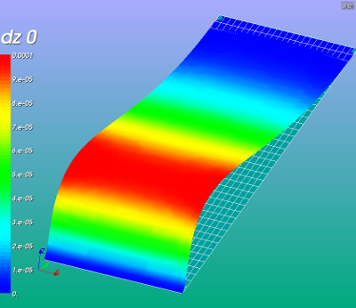
Results
All pictures below show the z deformation due to a pressure of 1000 [Pa].
Note that the mesh finess has been set to maximum ie. 1 instead of minimum 0 in the previous part.
-
 :
: 


left picture: shell thickness increases in positive y direction and undeformed mesh
right picture shows both increasing and decreasing shell thickness in positive y direction

detail of the maximum deformation
Clearly the solution is asymmetric due to the increasing thickness and hence stiffness of the shells in y direction.
Input files - download
- Media: kw_shell_list.zip
- Media: kw_variable_shell_thickness_v11p3.zip version 11.3
- Media: Kw variable thickness pressure v22.zip version 11.3
Input files:
- Python script for defining the geometry and mesh (geom_mesh_shell.py), load this file by File --> load script (cntrl T in the object browser), refresh (F5) after running. Change on line 11 the variable meshsize between 0.0 (course) and 1.0 (fine)
- Save the mesh by:
- change to Mesh module
- right clicking in the object browser by right clicking on the mesh name Mshell; select Export to MED
- change mesh file name to mshell.med and click save
- Save the mesh by:
- ASTK file (shellist.astk, you need to edit the path to your requirements ...). To start Code Aster calculation press Run. Interactive enabled, Interactive-follow-up disabled, nodebug enabled.
- command file (shell_static_d.comm), change sys.path.append('.....') for next file
- construct_shell_thickness Python file: place this file on your system and add the Python system path in your command file
- import sys #line 9
- sys.path.append('/<your_path_to_construct_shell_thickness>')
The last file also has a revised function for applying the thickness to the shells. Also a function for applying a variable pressure on the shell elements is provided. It uses the same procedure as for the variable thickness.

References
From Code Aster references:
[u2.02.01] Notice d’utilisation des éléments plaques, coques et coques volumiques SHB, Note of use of the voluminal elements plates, shells,
shells SHB, grids and Résumé
[u4.81.22] Opérateur POST_ELEM
[u5.02.00] Manuel d’Utilisation - Fascicule U5.0- : Structure de données resultat Document: U5.02.00 - Présentation des tables
[u3.12.03] Modélisation COQUE_3D
[R3.07.04] Eléments finis de coques volumiques, Finite elements of voluminal shells
[R3.07.05] Éléments de coques volumiques en non linéaire géométrique, Voluminal shell elements into nonlinear geometrical (i.e. machine translation France2Frenglish).
[u4.42.01] Opérateur AFFE_CARA_ELEM --8.3.1 EPAIS/EPAIS_F, Opérateur AFFE_CARA_ELEM
Code Aster forum - discussion:
[Code Aster forum] MAX number of GROUP_MAs & Variable shell thickness
[CA forum - 2 -this is a circular reference] coque à épaisseur variable
[More on Python and CA - by Bracchesimo] Structure Optimization with Code_Aster
--keeswouters november 2010 -- update januari 2013