Contrib:KeesWouters/beambuckling
Contents
Buckling behaviour of a beam
To start with, this contribution mainly focuses on the use of Salome and Code Aster, not on the results and the mechanical justifications of the code that has been used. So no garantees that the results will be correct upto the fifth decimal place, which they are not. I do hope though that this information is useful. For me it has been, because I had to think about some commands and look through the documentation and learn from that. In case of mistakes, errors and the like, please notify me, or better, you are invited to correct them yourself. Enjoy.
General discription of the calculation
First the geometry is defined in Salome. The mechanical properties and loads are defined in the C-Aster command file. In order to determine the geometrical stiffness matrix, a linear calculation is carried out and the corresponding stresses in the construction are determined.
The stiffness matrix is available from the linear case and can be extracted. The geometrical stiffness matrix can be derived from the calculated stresses in the construction. Finally an eigenvalue analysis is then carried out to determine the buckling load.
Critical load according to Euler
The construction is a prismatic beam with diameter 1 and length 50 mm. The material is steel. According to Euler the the critical load with fixed i.e clamped boundary conditions at both ends of the beam is
- Fcr = E*Iss*(pi/(k*L))^2,
- k = 0.5 for clamped boundary conditions
- Youngs' modulus E = 2.1e5 MPa
- poisson ratio nu = 0.28, not needed for the Euler beam
- smallest moment of inertia Iss = pi/64*d^4 = 0.049 mm4
- length of the beam L = 50 mm
- corresponding axial load Fax = Cz*Uz = EA/L * Uz = 3298.7 * 0.2 = 659.7 N
- Fcr = 162.8 N or a ratio of
- ratio = Fcr/Fax = 0.247
This last value is what we are looking for in the buckling analysis with Code-Aster.
Defining the properties of the beam
Geometry of the beam
-
 *
* 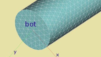


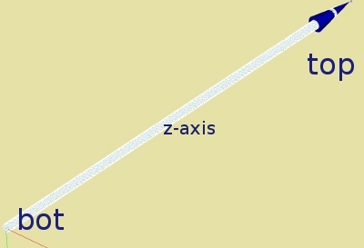
The construction is readily defined in the Geometry module of Salome by Cylinder, radius 0.5 and length 50 mm, at the origin of the coordinate system. The axial direction of the beam coincides with the global z axis. The two axial faces of the beam are denoted by 'bot' and 'top', used to apply boundary conditions and loads.
Beam with solid elements
The mesh is generated by NetGen. The choosen algorithm is tetrahedron (NetGen), NetGen 1D 2D 3D. The applied hypothysis are: Maximum volume 0.25, maximum size 0.125. Second order elements are generated, finess is moderate, and optimize is set. A face group is generated for top and bot. The boundary conditions will be dx=dy=dz=0 at the 'bot' and dx=dy=0, dz=-0.2 mm at 'top', see command file for this further on.
Material properties of the beam
The beam consists of steel. The material properties are as given above.
Result of Code-Aster
Linear load case for determining the stresses
First the linear load case has to be solved to determine the stresses in each element. Use the commands:
- result=MECA_STATIQUE(MODELE=pmodel,CHAM_MATER=matprops,EXCIT=(_F(CHARGE=FLoad,),),);
- result=CALC_ELEM(reuse=result, ...);
- result=CALC_NO(reuse =result, ...);
In order to verify the calculation we determine the force on the top plane. Since we applied a displacement on the top, we are interested in the corresponding axial force. On this plane, the extracted axial force is -660.4 N, slightly more than the analytic result.
The nodal forces, reaction forces and displacements of the top plane can be extracted from the result by defining a table and write them to a file:
pmesh=DEFI_GROUP(reuse=pmesh,MAILLAGE=pmesh,CREA_GROUP_NO=_F(NOM='top',GROUP_MA='top',),);
TB_nodf=POST_RELEVE_T(ACTION=(
         _F(OPERATION='EXTRACTION',..,NOM_CHAM='DEPL',..,GROUP_NO='top',..),
         _F(OPERATION='EXTRACTION',..,NOM_CHAM='FORC_NODA',..,GROUP_NO='top',.),..);
IMPR_TABLE(TABLE=TB_nodf,FORMAT='TABLEAU',UNITE=26,SEPARATEUR=' * ', ...);
The content of the file, again defined in ASTK:
#displacements at nodes on group top
#[Reaction] Nodal  Forces
* INTITULE         * RESU     * NOM_CHAM         * NUME_ORDRE   * INST         * DX           * DY           * DZ
* displacements    * result   * DEPL             *            1 *  0.00000E+00 * -7.30250E-19 * -3.47836E-17 * -4.08000E+01
* ReactionForces   * result   * REAC_NODA        *            1 *  0.00000E+00 *  2.83321E-06 *  8.20372E-06 * -6.60449E+02
* NodalForces      * result   * FORC_NODA        *            1 *  0.00000E+00 *  2.83321E-06 *  8.20372E-06 * -6.60449E+02
Element stiffness matrix and geometrical stiffness matrix
...
Eigenvalue extraction by Sorensen iteration
CALCUL MODAL:  METHODE D'ITERATION SIMULTANEE
                     METHODE DE SORENSEN
NUMERO    CHARGE CRITIQUE    NORME D'ERREUR
   1      -9.72998E-01       3.68322E-09
   2      -9.72990E-01       3.42967E-09
   3      -5.00953E-01       5.82225E-09
   4      -5.00949E-01       6.01805E-09
   5      -2.45979E-01       3.26885E-08
   6      -2.45977E-01       3.10062E-08
NORME D'ERREUR MOYENNE:  0.13775E-07
The bold values of modes 5 and 6 nicely correspond with the analytic values 0.247 found earilier. Note:
- The way C-Aster calculates the eigenvalue problem causes a change of sign for the eigenvalue (see references at the end).
- Modes 5 and 6 are the lowest eigenvalues of the total extracted 6 values. These are of course the critical values of the buckling analysis.
- Modes 5 and 6 (and 3 - 4 and 1 - 2) are the same modes in the x and y directions.
References
- Opérateur MODE_ITER_SIMULT: http://www.code-aster.org/V2/doc/v9/man_u/u4/u4.52.03.pdf
- Opérateur MODE_ITER_INV: http://www.code-aster.org/V2/doc/v9/man_u/u4/u4.52.04.pdf
- Opérateur MACRO_MATR_ASSE: http://www.code-aster.org/DOCASTER/Man_U/U4/U46121g1.pdf
- Opérateur ASSE_MATRICE: http://www.code-aster.org/DOCASTER/Man_U/U4/U46122h.pdf
- Opérateur NUME_DDL: http://www.code-aster.org/V2/doc/v9/man_u/u4/u4.61.11.pdf
MODE_ITER_SIMULT, paragraph 3.1:
La recherche de mode de flambement linéaire. Dans le cadre de la
théorie linéarisée, en supposant a priori que les phénomènes de stabilité sont
convenablement décrits par le système d'équations obtenu en supposant la
dépendance linéaire du déplacement par rapport au niveau de charge critique,
la recherche du mode de flambement x associé à ce niveau de charge critique
mu = -, se ramène à un problème généralisé aux valeurs propres de la forme
- (Kmu*Kg*x=0 ⇔ K*x =Kg*x
- K = A, (stiffness matrix)
- Kg = B, (geometrical stiffness matrix)
K matrice de rigidité matérielle et Kg matrice de rigidité géométrique. Les modes avec propres manipulés (l,x) sont à valeurs réelles. Ce type de
problématique est activé par le mot-clé TYPE_RESU='FLAMBEMENT' et génère une
structure de données Aster de type mode_flamb.
Attention:
• Dans le code, on ne traite que les valeurs propres du problème
généralisé, les Pour obtenir les véritables charges critiques, les mu, il
faut les multiplier par –1.
• En GEP, pour traiter des problèmes à modes complexes (matrices non
symétriques et/ou à valeurs complexes), il faut utiliser
MODE_ITER_SIMULT ('METHODE='SORENSEN'/'QZ').