Difference between revisions of "Contrib:KeesWouters/beam/orientation"
Keeswouters (Talk | contribs) m (→'''References''') |
Keeswouters (Talk | contribs) m (→'''References''') |
||
| Line 191: | Line 191: | ||
[[http://www.code-aster.org/DOCASTER/Man_U/U5/U50200b.pdf u5.02.00]] Manuel d’Utilisation - Fascicule U5.0- : Structure de données resultat Document: U5.02.00 - Présentation des tables<br/> | [[http://www.code-aster.org/DOCASTER/Man_U/U5/U50200b.pdf u5.02.00]] Manuel d’Utilisation - Fascicule U5.0- : Structure de données resultat Document: U5.02.00 - Présentation des tables<br/> | ||
[[http://www.code-aster.org/V2/doc/v9/man_u/u4/u4.42.01.pdf u4.42.01]] Opérateur AFFE_CARA_ELEM --6.1, 6.2, 6.3 and chapter 9 <br/> | [[http://www.code-aster.org/V2/doc/v9/man_u/u4/u4.42.01.pdf u4.42.01]] Opérateur AFFE_CARA_ELEM --6.1, 6.2, 6.3 and chapter 9 <br/> | ||
| − | [[http://www.code-aster.org/V2/doc/v9/man_u/u3/u3.11.01.pdf u3.11.01]] Modélisations POU_D_T, POU_D_E, POU_C_T, BARRE | + | [[http://www.code-aster.org/V2/doc/v9/man_u/u3/u3.11.01.pdf u3.11.01]] Modélisations POU_D_T, POU_D_E, POU_C_T, BARRE<br/> |
[[http://www.code-aster.org/forum2/viewtopic.php?id=14788 probleme avec une simple reévaluation de valeur]] | [[http://www.code-aster.org/forum2/viewtopic.php?id=14788 probleme avec une simple reévaluation de valeur]] | ||
--[[User:Keeswouters|keeswouters]] januari 2011 | --[[User:Keeswouters|keeswouters]] januari 2011 | ||
Revision as of 12:43, 30 January 2011
Contents
- 1 Static displacement of a simple beam on point load
- 2 Define orientation of beam elements by Python list
- 3 Geometry, mesh, material properties and loads
- 4 General way to define the orientation of the beam
- 5 Define a beam element by standard commands
- 6 Define the orientation of the beam by a Python list
- 7 Numerical results
- 8 Finally - results
- 9 Input files - download
- 10 References
Static displacement of a simple beam on point load
januari 2011 - SalomeMeca 2010 (Code Aster 10.2) - Ubuntu Meerkat 10.10 64bits.
Define orientation of beam elements by Python list
If you are already familiar to Code Aster, enjoy this. Otherwise start with a less complicated example, eg have a look here first please.
The command file beam1.comm together with beam1.astk could be a nice start though -see end of this contribution.
Geometry, mesh, material properties and loads
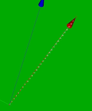
This is just a simple example of the use of beams for static calculations. The main focus is on varying orientation of the beam by a Python list. The orientation of the beams depend on the x coordinate of the beam element.
The cross section of the beams is a rectangle defined by HY, HZ and EP, ie the height in y and z direction and the wall thickness respectively. Length of the beam is 1.41 [m].
The mesh consists of about thirty beam elements distributed along the x axis. This has the curious effect that the coordinates of the nodes are defined by a single coordinate. Mind that you need to adapt the code in case of two or three dimensional coordinates (see define_beam_orient, see also *) there]).
#Read MED mesh file
BeamMesh=LIRE_MAILLAGE(UNITE=20,
                       FORMAT='MED',
                       #NOM_MED='Mesh_1',
                       INFO_MED=2,
                       INFO=2,);
The boundary conditions are: fully clamped at x = 0, free at the opposite end. The load consist of a nodal force in x (axial load of 1 [N] and a shear force of 2 [N] in y direction on the end node:
BndCnd=AFFE_CHAR_MECA(MODELE=BeamMod,
                        DDL_IMPO=(
                         _F(GROUP_NO='P1',DX=0.0,DY=0.0,DZ=0.0,DRX=0.0,DRY=0.0,DRZ=0.0,),),
                        FORCE_NODALE=
                         _F(GROUP_NO='P2',FX=1.0,FY=2.0,),);
General way to define the orientation of the beam
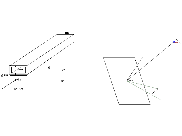
The geometry and mesh are generated in Salome in the standard way. In Code Aster the mesh is read, including nodes number, node coordinates, element types and element connectivity. We use linear seg2 elements for the beams.
Of each element we can
- determine the nodes by the connectivity matrix,
- determine the x coordinates of the nodes and
- generate the orientation of the beam
by Python commands.
-
 *
* 
-
 *
*


Define a beam element by standard commands
After reading the mesh file the following two commands define the beam elements in a standard way:
#Assign to the Model
BeamMod=AFFE_MODELE(MAILLAGE=BeamMesh,
                   AFFE=_F(##TOUT='OUI',
                           GROUP_MA='beam1',
                           PHENOMENE='MECANIQUE',
                           MODELISATION='POU_D_T',),);
#Characteristics of Elements, now combined
Beam1=AFFE_CARA_ELEM(MODELE=BeamMod,
                     POUTRE=(_F(GROUP_MA='beam1',
                               SECTION='RECTANGLE',
                               CARA=('HY','HZ','EP',),
                               VALE=(0.0200,0.0100,0.0025,),),),
                     ORIENTATION=(_F(GROUP_MA='beam1',
                                    CARA='VECT_Y',
                                    VALE=(0.0,0.0,1.0,),),),)
The first command AFFE_MODELE(...) defines a beam model 'POU_D_T' for a the seg2 elements in the group GROUP_MA='beam1'.
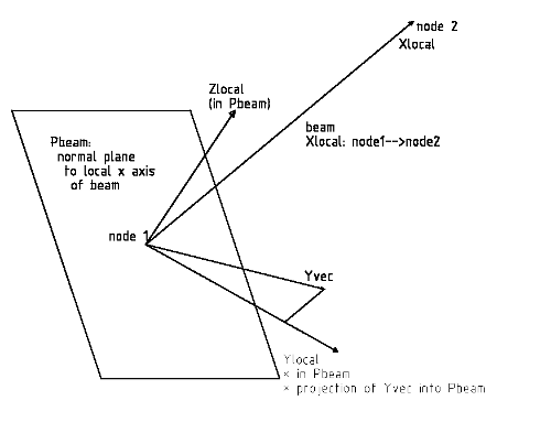
The second command AFFE_CARA_ELEM defines the geometrical quantities of the beam: in this case a rectangular cross section with width HY and height HZ. The wall thickness is defined by EP. The orientation of the beam is defined by the ORIENTATION parameter for all beams of GROUP_MA='beam1'. We define the local y vector by CARE='VECT_Y' and the vector VALE=(0.0,0.0,1.0). Note that the local x axis is defined by the axial direction of the beam (X = (P2-P1) where P1 and P1 are the nodes of the beam). The projection of the vector VECT_Y (with VALE=[vx,vy,vz]) defines the local y axis of the beam. Then of course the local z axis is defined as well.
Here is an uncensored copy of U3.11.01 Modélisations POU_D_T, POU_D_E, POU_C_T, BARRE:
Principales caractéristiques des modélisations
- La modélisation POU_D_E (Poutre Droite d’Euler) correspond à l'hypothèse d'Euler-Bernouilli, c'est-à-dire que les sections restent droites et perpendiculaires à la fibre moyenne (hypothèse de grand élancement).
- La modélisation POU_D_T (Poutre Droite de Timoshenko) prend en compte les effets de cisaillement transverse.
- La modélisation POU_C_T est analogue à POU_D_T avec une courbure (Poutre Courbe de Timoshenko).
- La modélisation BARRE ne traite que les efforts et déformations axiales. La poutre avec gauchissement est traitée en [U3.11.04].
Define the orientation of the beam by a Python list
The orientation part of the command
 AFFE_CARA_ELEM(MODELE(.....
                       ORIENTATION=(_F(GROUP_MA='beam1',
                                       CARA='VECT_Y',
                                       VALE=(0.0,0.0,1.0,),),),)
can be caught in a Python list as follows:
OrientBeam = ({'MAILLE': 'M1', 'CARA': 'VECT_Y', 'VALE': [0.0, y_vecty, z_vecty]})
where GROUP_MA is replaced by 'MAILLE' and the remaining parameters are identical. The y and z components of vector VECT_Y depend on the position of the beam. For the complete list we have in this case:
OrientBeam:
 [{'MAILLE': 'M1', 'CARA': 'VECT_Y', 'VALE': [0.0, 0.6473, 0.7621]},
  {'MAILLE': 'M2', 'CARA': 'VECT_Y', 'VALE': [0.0, 0.4198, 0.9075]},
  ....
  {'MAILLE': 'M28', 'CARA': 'VECT_Y', 'VALE': [0.0, 0.8835, 0.4684]},
  {'MAILLE': 'M29', 'CARA': 'VECT_Y', 'VALE': [0.0, 0.3701, 0.9289]}]
In 'pseudo' Python code:
## define mesh quantities
meshCA   = MAIL_PY()
meshCA.FromAster(mesh);
nonu     = meshCA.dime_maillage[0]
elnu     = meshCA.dime_maillage[2]
ncoord   = meshCA.cn
connect  = meshCA.co
xmax = numpy.max(ncoord)
OrientBeam=[]
vy = [None]*BeamCount   # initialise VECT_Y
BeamCount = 0
for ii in xrange(len(ElemList)):
    if (info==2):
      print 'elementtype: ',ii,ElemType[ii]
    if ElemType[ii]==2:  # select seg1
      ncount = len(connect[ii])          # could be 1,2,3 for beam (elementType 2)  *)
      sumxyz = 0.0*ncoord[connect[ii][0]]  # init xumxyz to zero - 'size('ncoord')'
      for jj in xrange(0,ncount):
        Gnode = connect[ii][jj]    # globalnode = connect[elemii,internal_nodejj]
        sumxyz += ncoord[Gnode]    # this might be written more compact --> for later
        print 'connectivity: ',Gnode
        print 'ncoord:       ',ncoord[Gnode]
      xaverage = sumxyz/ncount   # average coord
      print 'xaverage: ',xaverage[0]
      phase = math.pi/2.0*xaverage[0]/xmax
      print 'phase: ',phase
      y_vecty = math.cos(phase)
      z_vecty = math.sin(phase)
      vy = [0.000000, y_vecty, z_vecty]
      OrientBeam.append({'CARA':'VECT_Y','VALE':vy,'MAILLE':'M%d'%(ii+1)});
The phase parameter, sin() and cos() functions make sure that the orientation gradually rotates from Vy = Yglob = [0,1,0] at the beginning to Vy = Zglob = [0,0,1] at the end of the beam. Note that the mesh numbering is quite mixed up in Code Aster, so 'M1' is not the beam element with the lowest x coordinate.
The code above is defined in a python file define_beam_orient.py and is called by the Code Aster command file:
ob = define_beam_orient(BeamMesh,1);
print 'ob: ', ob
#Assign to the Model
BeamMod=AFFE_MODELE(MAILLAGE=BeamMesh,AFFE=_F(##TOUT='OUI',
                           GROUP_MA='beam1',PHENOMENE='MECANIQUE',
                           MODELISATION='POU_D_T',),);
# orientation replaced by list:
Beam1=AFFE_CARA_ELEM(MODELE=BeamMod,
                     POUTRE=(_F(GROUP_MA='beam1',SECTION='RECTANGLE',CARA=('HY','HZ','EP',),VALE=(0.200,0.0100,0.0025,),),),
                     ORIENTATION=ob,);
Numerical results
Comparing the C-Aster displacements of the end node to the standard 'vergeet-me-nietjes' of a clamped beam we orient the local y axis of the beam once to the global y axis and once to the global z axes ('neglecting' the normal force of Fnormal = 1 [N] used in the Code Aster calculation):
   local y axis      global      Fy   'vergeet-me-nietjes'  CA-dy        CA-dz
1) y-axis            Glob y      2.0   6.1352e-04           6.1357E-04   0.0
2) y-axis            Glob z      2.0   2.5101e-06           2.5606E-06   0.0
3) y-axis            rotating    2.0    <...>               1.2243E-04  -1.7370E-04
for 1) and 2) the result in y direction correspond to 4 significant numbers.
In case of the rotating VECT_Y 3) the results is in between 1) and 2) and could be correct (if anyone is willing the verify ...).
'vergeet-me-nietjes' equation: dy = F*L^3/(3*E*Iss) where
F = 2.0 [N]
L = sqrt(2) ~ 1.41421 [m]
E = 210 [GPa]
Iss is either, depending on the orientation of the beam
  Iyy =  3.5771e-06 [mm4]
  Izz =  1.4635e-08 [mm4]
Iyyo = bo*ho^3/12
Iyy1 = b1*h1^3/12
Iyy  = Iyyo - Iyy1 and the same calculation for Izz, but changing b and h.

bo = HZ        ho = HY
b1 = HZ-2*EP   h1 = HY-2*EP for rectangle cross section with rectangle hole, wall thickness EP
Now depending on the choice of the orientation vector VECT_Y, you may substitute Iyy or Izz for Iss in the equation of the v'vergeet-me-nietjes'.
Finally - results
For a complete list of commands, see the download part at the end. The command file beam1.comm is the standard Code Aster command file. The orientation of the beams are fixed in one direction. Command file beam2.comm uses the python list and needs the python script define_beam_orient.py.

Because of the asymmetric cross section and changing orientation of the beam along the x axis, the beam will have an 'out of plane' displacement.
Input files - download
Input files:
- Python script for defining the geometry and mesh (line.py), load this file by File --> load script (cntrl T in the object browser), refresh (F5) after running.
- Save the mesh by:
- change to Mesh module
- right clicking in the object browser by right clicking on the mesh name Mline1; select Export to MED
- change mesh file name to mline1.med and click save
- Save the mesh by:
- two ASTK files (beam1.astk and beam2.astk, you need to edit the path to your requirements ...). To start Code Aster calculation press Run. Interactive enabled, Interactive-follow-up disabled, nodebug enabled. Beam1.astk run the conventional command file, beam2.astk runs the python list.
- two command files (beam1.comm and beam2.comm), change sys.path.append('.....') for next file. Same remark as ASTK file.
- define_beam_orient.py Python file: place this file on your system and add the Python system path in your command files (beam1.comm and beam2.comm):
- import sys #line 5
- sys.path.append('/<your_path_to_define_beam_orient>')
References
[varying plate thickness], for a similar approach for varying thickness of shell elements
[u5.02.00] Manuel d’Utilisation - Fascicule U5.0- : Structure de données resultat Document: U5.02.00 - Présentation des tables
[u4.42.01] Opérateur AFFE_CARA_ELEM --6.1, 6.2, 6.3 and chapter 9
[u3.11.01] Modélisations POU_D_T, POU_D_E, POU_C_T, BARRE
[probleme avec une simple reévaluation de valeur]
--keeswouters januari 2011