Difference between revisions of "Contrib:KeesWouters/bc/rbe3"
Keeswouters (Talk | contribs) m (→Geometry and mesh of the block with cylindrical hole) |
Keeswouters (Talk | contribs) (→Geometry and mesh of the block with cylindrical hole) |
||
| Line 14: | Line 14: | ||
The centre 0D nodes is the master node to apply the constraint to the nearby surface. | The centre 0D nodes is the master node to apply the constraint to the nearby surface. | ||
| + | |||
| + | =='''Definition of node groups'''== | ||
| + | Mcyl=DEFI_GROUP(reuse =Mcyl, | ||
| + | MAILLAGE=Mcyl, | ||
| + | CREA_GROUP_NO=_F(NOM='Nbot',GROUP_MA='Abot',),); | ||
| + | |||
| + | Mcyl=DEFI_GROUP(reuse =Mcyl, | ||
| + | MAILLAGE=Mcyl, | ||
| + | CREA_GROUP_NO=_F(NOM='Nmaster',GROUP_MA='Pmaster0',),); | ||
| + | |||
| + | |||
| + | =='''Definition of node groups'''== | ||
| + | CylModel=AFFE_MODELE(MAILLAGE=Mcyl, | ||
| + | AFFE=(_F(TOUT='OUI', | ||
| + | PHENOMENE='MECANIQUE', | ||
| + | MODELISATION='3D',), | ||
| + | _F(GROUP_NO='Nmaster', | ||
| + | PHENOMENE='MECANIQUE', | ||
| + | MODELISATION='DIS_TR',),),); | ||
Revision as of 21:29, 18 February 2013
Geometry and mesh of the block with cylindrical hole
This construction shows the RBE3 constraint. This is used to apply a moment to the top surface of a cylinder. The bottom surface of the cylinder is fixed 3dof to the world. The inner and outer diameters of the cylinder are 15 and 17 (arbitrairy units) and length 75. The used material is steel, material properties are in ISO units (this makes the dimensions of the cylinder ISO as well).
The geometrical entities on the cylinder are, A for surface areas:
- Atop and
- Abot
Abot is used to apply the torsion moment, Atop is used to apply the fixed boundary condition to the 'world'.
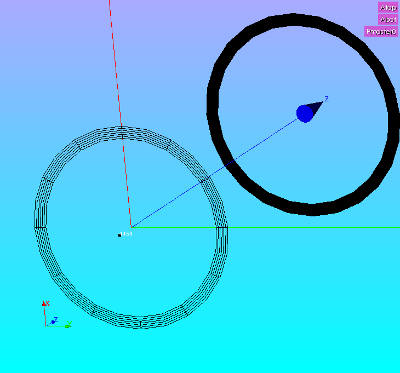
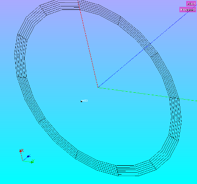
Some images of the construction of the geometry and mesh:
The mesh is divided in 13 divisions in axial direction. In radial direction 6 divisions are present and in tangential direction two times 6 divisions are made. Later on we will modify this last mesh.
The centre 0D nodes is the master node to apply the constraint to the nearby surface.
Definition of node groups
Mcyl=DEFI_GROUP(reuse =Mcyl,
                MAILLAGE=Mcyl,
                CREA_GROUP_NO=_F(NOM='Nbot',GROUP_MA='Abot',),);
Mcyl=DEFI_GROUP(reuse =Mcyl,
                 MAILLAGE=Mcyl,
                 CREA_GROUP_NO=_F(NOM='Nmaster',GROUP_MA='Pmaster0',),);
Definition of node groups
CylModel=AFFE_MODELE(MAILLAGE=Mcyl,
                     AFFE=(_F(TOUT='OUI',
                              PHENOMENE='MECANIQUE',
                              MODELISATION='3D',),
                           _F(GROUP_NO='Nmaster',
                              PHENOMENE='MECANIQUE',
                              MODELISATION='DIS_TR',),),);

