Contrib:Claws/Code Aster/10 x cases/torque
Content
Introduction
Torque
Code_Aster does not (yet anyway) have a straight forward way of applying torque to a structure. Only nodes have the option of having moment (FORCE_NODALE-> MX,MY and MZ) applied to them. What this means is, that you, in order to apply torque to an object, have to connect a single node to the object and and thereby transfer the moment into torque.
There are several ways of achieving this, but I will only describe one of the ways here. In terms of what happens inside Code_Aster, this method places a single node adjacent to the surface you want to apply torque to, creates a rigid link between the single node and the surface and finally applies the moment and thereby torque.
- Surface (Node group of surface)
- Create adjacent single node
- Code_Aster creates rigid links between the node and the surface
- Apply moment to single node
=Achieving this in Salomé
(You should be familiar with creating a geometry and meshing it already)
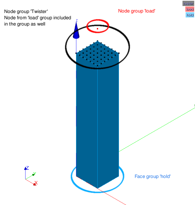
Not much to explain here since it is described well in the image below.
Mesh your object and create a single node center and normal to the surface you want to apply torque to. In this case it makes sense to create it with an offset normal to the surface so it's easier to select the single node. Assign a 'node group' to the single node
The surface you want to apply torque to, must be assigned to a 'node group' and not a 'surface group' (important).
Finally, assign a surface group (or which ever you prefer) to the surface that will prevent the object from moving. Here the bottom of the object.
Parameters
Using parameters in Code_Aster is as useful as in any situation; it lets you change many variables at once and can let you control an entire calculation by changing only one parameter.
In this case one parameter is used to do just that: T1
- T1=10
- T2=(2*T1)
- T3=(3*T1)
- T4=(4*T1)
- NBT=T1 (or any of the Tx)
- T_END= Any of the Tx
By changing the value of T1 you change the number of steps (resolution) in the calculation and the length of the calculation.
By using a value of 10 for T1, 10 steps is calculated for each interval, and with 4 intervals 40 calculations is done. Using T1=100 increases the resolution and length by an order of 10.
The parameter NBT determines the number of steps for each interval so with NBT=T1 the number of steps becomes 10
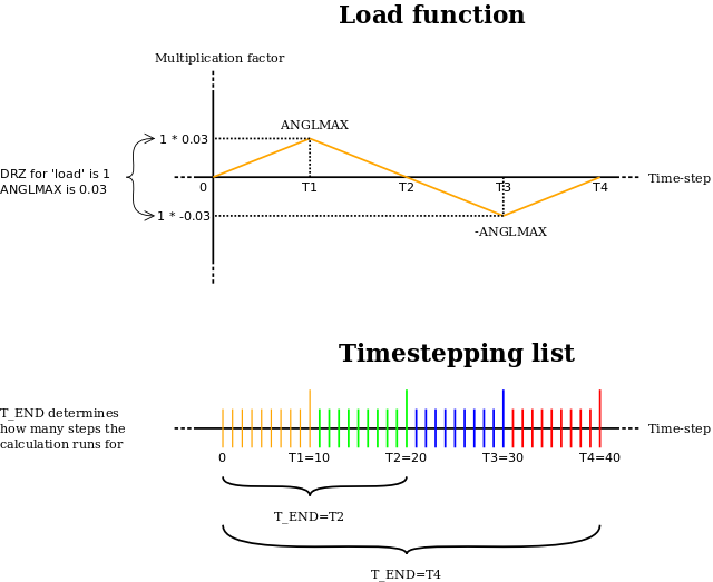
The parameter T_END determines for how many steps the entire calculation should run for. In other words; it determines how many intervals are calculated, e.g. T_END=T1 means 10 steps are calculated and outputted and with T_END=T4, 40 steps are calculated and outputted.
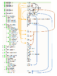
I've tried to visualize the influence of the parameters in this diagram (click to view full image)
The load multiplier is also connected to T1 and thus follows the number of steps you increase or decrease (but not the magnitude of the load) The parameter ANGLMAX is used to determine the maximum magnitude of the load (angle of twist) in the object.
In the following diagram, the function for the load and the intervals of the calculation is visualized.


