Difference between revisions of "Contrib:Claws/Code Aster/10 x cases/liaison mail"
| Line 14: | Line 14: | ||
[[Image:Claws_assm_geo.jpg]] | [[Image:Claws_assm_geo.jpg]] | ||
| − | + | == Work flow == | |
| − | To accomplish this feat using Salomé, ASTK and Code_Aster, a few steps must be completed. | + | To accomplish this feat using '''Salomé''', '''ASTK''' and '''Code_Aster''', a few steps must be completed. |
*Decide which surfaces of the parts that will be 'glued' together and assign mesh groups accordingly | *Decide which surfaces of the parts that will be 'glued' together and assign mesh groups accordingly | ||
| − | *Assign unit numbers in ASTK | + | *Assign unit numbers in '''ASTK''' |
| − | *Tell Code_Aster which mesh files to | + | *Tell '''Code_Aster''' which mesh files to read using unit numbers and tell it which surfaces that should be glued together. |
| Line 45: | Line 45: | ||
<br style="clear: both" /> | <br style="clear: both" /> | ||
| − | === Assignment of groups === | + | === Assignment of groups in Salomé === |
| + | |||
| + | You should be familiar with assigning groups, meshing and exporting files in Salomé, so I will not go through it here. Consult the '''.hdf''' file I've attached at the bottom of the page. | ||
---- | ---- | ||
| Line 57: | Line 59: | ||
<br style="clear: both" /> | <br style="clear: both" /> | ||
| + | === ASTK setup === | ||
| − | + | === Code_Aster setup === | |
| + | |||
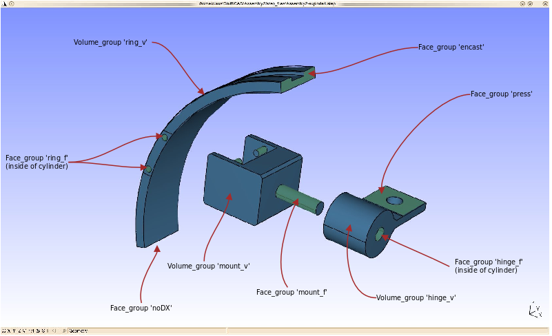
| + | The way Code_Aster connects different meshes, is by using the '''LIAISON_MAIL''' command. A 3D volume group is connected to a 2D face group using a 'parent/child' relationship called ''GROUP_MA_MAIT'' and ''GROUP_MA_ESCL'' - this explains why the parts in the group diagram (in the Salomé paragraph) are assigned groups called ''name'''_f''' '' for face and ''name'''_v''' '' for volume. | ||
| − | The | + | Heres a diagram of the boundary conditions - The will be explained further in the ''.comm'' file. |
[[Image:Claws_load_diagram.png|left|frame|Load and boundary conditions diagram]] | [[Image:Claws_load_diagram.png|left|frame|Load and boundary conditions diagram]] | ||
Revision as of 02:49, 5 February 2010
<-Link: Back to Contrib:Claws/Code_Aster/10_1_x_cases
Contents
Content
Introduction and theory
In this case we'll use ASTK and Code_Aster to load and combine several separate mesh files into one big mesh and solve for an applied load. The reasons for this approach can be many, but sometimes it's just more practical to work on one part of an assembly instead of the full assembly.
In Salomés geometry module the full assembly is manipulated in different ways, but each of the parts are meshed and exported separately.
A section of the assembly below, is what we'll be working with.

Work flow
To accomplish this feat using Salomé, ASTK and Code_Aster, a few steps must be completed.
- Decide which surfaces of the parts that will be 'glued' together and assign mesh groups accordingly
- Assign unit numbers in ASTK
- Tell Code_Aster which mesh files to read using unit numbers and tell it which surfaces that should be glued together.
Below in the table the different parts that go into the assembly can be seen.
| Tables | Are | Fun |
|---|---|---|
 |


Assignment of groups in Salomé
You should be familiar with assigning groups, meshing and exporting files in Salomé, so I will not go through it here. Consult the .hdf file I've attached at the bottom of the page.
<br\>

ASTK setup
Code_Aster setup
The way Code_Aster connects different meshes, is by using the LIAISON_MAIL command. A 3D volume group is connected to a 2D face group using a 'parent/child' relationship called GROUP_MA_MAIT and GROUP_MA_ESCL - this explains why the parts in the group diagram (in the Salomé paragraph) are assigned groups called name_f for face and name_v for volume.
Heres a diagram of the boundary conditions - The will be explained further in the .comm file.

<br\>
| Tables | Are | Fun |
|---|---|---|
| row 2, cell 2 | row 2, cell 3 |


