Contrib:Claws/Code Aster/10 x cases/liaison elem
<-Link: Back to Contrib:Claws/Code_Aster/10_1_x_cases
Contents
Content
Introduction and theory
Code_Aster has the ability to connect elements of different dimensions. 0-1-2 and 3D elements can be connected together in all different manners, but in this particular study, we'll connect 3D elements to 1D elements and back to 3D again.
In many situations this can drastically reduce the work load on the computer doing the analysis, not to mention post-processing the files afterwards.
In a situation where you're only interested in what happens at the boundaries, theres no need to model and calculate the areas inbetween.
The way to go about this, is to describe the area inbetween, instead of modeling it.
For this feat, Code_Aster provides a powerful command called LIAISON_ELEM.
(Document U4.42.01 describes this command fully)
To describe an element, C_A need know how many degree of freedom the element have and what the element geometrically looks like.
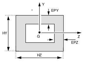
For this a model must be assigned to the element, and parameters for the geometry must be assigned. Heres an example of how a square pipe is described:
In this study we're using a solid rectangle so we only need to assign the parameter H since the sides are of equal length.
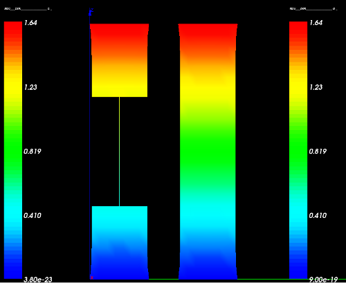
This is the result of we'll be working towards in this study
Applying the theory to C_A
Preparing the object
In this study we'll analyze the boundary conditions of a column, substituting the middle of the column with a 1D element and describing this element to C_A, thus saving a lot of computing time. Actually not at all, really. Since the geometry in this situation is so simple, we're talking mere mili-seconds and roughly 1mb of RAM saved - we'll do it anyway just for the heck of it.
From looking at the image of the result, you should have a good idea of how to model the situation.
- Create two boxes of 200x200x200 in the geometry modules of Salomé, enter the mesh module.
- In the mesh module, mesh the two boxes individually with hexahedrons.
- Create a compound mesh of the two boxes. Right click the compound mesh and select 'show only'
- Now create two points; one at the center of the top surface of the bottom box (if the box is 200x200x200, the coordinates of the first point will be {100,100,200}), and another at the center of the bottom surface of the top box.
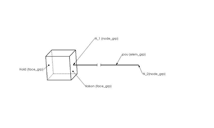
- Create a node group for each of the two nodes, call the two nodes N_1 and N_2
- Create an edge by using the two points you just created. Assign this to an element group and call it bar
- The surfaces that are to be connected with the edge just created, are assigned face groups and are called liaison and liaison2, respectively.
- Bottom face of the bottom box is assigned a face group called hold, top face of the 'top' box is assigned a face group called top
- Heres a picture of what it should look like (only the bottom box is showed though)
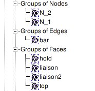
Now you should have a constellation of groups looking something like this:
Export the mesh to a .med file and we are ready to move on to...
Applying LIAISON_ELEM in Code_Aster
Walking through the .comm file step by step
DEBUT();

MA=DEFI_MATERIAU(ELAS=_F(E=210e+03,
                        NU=0.28,),);

MAIL=LIRE_MAILLAGE(FORMAT='MED',
                  INFO_MED=1,);
Define the material, read the mesh
MODE=AFFE_MODELE(MAILLAGE=MAIL,
                AFFE=(_F(TOUT='OUI',
                         PHENOMENE='MECANIQUE',
                         MODELISATION='3D',),
                      _F(GROUP_MA='bar',
                         PHENOMENE='MECANIQUE',
                         MODELISATION='POU_D_E',),),);
- Definition
- Assign a 3D model to everything, call it MODE
- Assign a beam model with 3D capabilities (rotation and translation) to the element bar
- POUtre = beam, Droite = straight, Euler hypothesis
- See U3.11.01 section 1 for further definition
- POUtre = beam, Droite = straight, Euler hypothesis
MATE=AFFE_MATERIAU(MAILLAGE=MAIL,
                  AFFE=_F(TOUT='OUI',
                          MATER=MA,),);
- Definition
- Assign the material to everything
cara=AFFE_CARA_ELEM(MODELE=MODE,
                   VERIF=('NOEUD','MAILLE',),
                   POUTRE=_F(GROUP_MA='bar',
                             SECTION='RECTANGLE',
                             CARA='H',
                             VALE=200.0,),);
- Definition


