Contrib:KeesWouters/bc/rbe3
Contents
- 1 Purpose of the RBE3 constraint
- 2 Geometry and mesh of the block with cylindrical hole
- 3 Definition of node groups
- 4 Definition of solid and discrete model
- 5 Coupling the node by 3D_POU
- 6 Coupling the node by RBE3
- 7 Results - displacements
- 8 Asymetric mesh
- 9 Input files for the FE Analysis and references
Purpose of the RBE3 constraint
[under construction]
RBE3
RBE3 defines a constraint relation in which the motion of a reference grid point is the least square weighted average of the motion at other grid points. The element is useful for beaming loads and masses of a reference point to a set of grid points
(from [[1]] NX Nastran Element Library Reference.
See also this [[2]link.]
A RBE3 constraint maybe useful, amongst others:
- to distribute a load to a set of nodes without the need of a rigid body constraint or
- to connect different bodies to each other without generating additional rigid body constraints.
Geometry and mesh of the block with cylindrical hole
This contribution shows the behaviour of the RBE3 constraint. In this case it is used to apply a moment to the top surface of a cylinder. The bottom surface of the cylinder is fixed 3dof to the world. The inner and outer diameters of the cylinder are 15 and 17 (arbitrairy units) and length 75. The material is steel, material properties are in ISO units (this makes the dimensions of the cylinder ISO as well).
Edit:
Apart from a RBE3 constraint it is possible to use a LIAISON_ELEM with OPTION='3D_POU' to connect one master node to a set of nodes without applying additional rigid body constraints. This has been added later in this contribution.
The geometrical entities on the cylinder are, A for surface areas:
- Atop and
- Abot
Abot is used to apply the torsion moment, Atop is used to apply the fixed boundary condition to the 'world'.
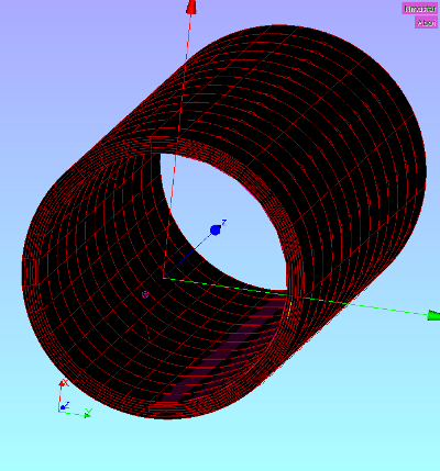
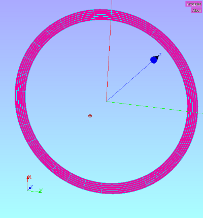
Some images of the construction of the geometry and mesh:


The mesh is divided in 13 divisions in axial direction. In radial direction 6 divisions are present and in tangential direction two times 6 divisions are made. Later on we will modify this mesh to construct some asymmetry into it.
The centre 0D nodes is the master node to apply the constraint to the nearby surface.
Definition of node groups
Mcyl=DEFI_GROUP(reuse =Mcyl,
                MAILLAGE=Mcyl,
                CREA_GROUP_NO=_F(NOM='Nbot',GROUP_MA='Abot',),);
Mcyl=DEFI_GROUP(reuse =Mcyl,
                 MAILLAGE=Mcyl,
                 CREA_GROUP_NO=_F(NOM='Nmaster',GROUP_MA='Pmaster0',),);
Definition of solid and discrete model
CylModel=AFFE_MODELE(MAILLAGE=Mcyl,
                     AFFE=(_F(TOUT='OUI',
                              PHENOMENE='MECANIQUE',
                              MODELISATION='3D',),
                           _F(GROUP_NO='Nmaster',
                              PHENOMENE='MECANIQUE',
                              MODELISATION='DIS_TR',),),);
N_stmass=AFFE_CARA_ELEM(MODELE=CylModel,
                        INFO=2,
                         DISCRET=(_F(CARA='M_TR_D_N',
                                     GROUP_NO='Nmaster',
                                     VALE=[0.0,0.0,0.0,0.0,0.0,0.0,0.0,0.00,0.00,0.00]),
                                 _F(CARA='K_TR_D_N',
                                    GROUP_NO='Nmaster',
                                    VALE=[0.0,0.0,0.0,0.0,0.0,0.0]),),);
Since the node apparently does not have any degrees of freedom, we need to apply a discrete element MODELISATION='DIS_TR' to the master node Pmaster. This is an element that carries mass and stiffness, but all entities have been set to zero in the value assignment, see DISCRET and VALE in the statement above. Then effectively only a node with translational and rotational degrees of freedom remains.
The command part
DISCRET_F(CARA='M_TR_D_N',GROUP_NO='Nmaster',VALE=[0.0,0.0,0.0,0.0,0.0,0.0,0.0,0.00,0.00,0.00]),
defines:
- the mass properties M_TR_D_N for
- the node 'Nmaster' (a single node need to be applied to the GROUP_NO), and
- the VALE group defines the mass m and Ixx, Iyy, Izz, Ixy, Iyx and Izx and three eccentricities:
- VALE=[m,Ixx,Iyy,Izz,Ixy,Iyz,Izx,Ecx,Ecy,Ecz]
The command part
DISCRET_F(CARA='K_TR_D_N',GROUP_NO='Nmaster',VALE=[0.0,0.0,0.0,0.0,0.0,0.0]),
defines:
- the stiffness properties K_TR_D_N for
- the node 'Nmaster' (a single node may to be applied to the GROUP_NO), and
- the VALE group defines the stiffnesses Kx, Ky, Kz, Krotx, Kroty and Krotz, all set to zero:
- VALE=[Kx,Ky,Kz,Krotx,Kroty,Krotz]
Coupling the node by 3D_POU
the coupling between a line element and a massive 3D body can be achieved by the LIAISON_ELEM with OPTION='3D_POU'. The nice part here is that the line part may be degradated to a single node. Normally you should select a node of a beam element and the nodes of the connecting face of the 3D body to link to each other. Here we select the master node Nmaster as GROUP_NO_2 and (the nodes of) the axial face as GROUP_MA_1. In detail the command is:
node3D=AFFE_CHAR_MECA(INFO=1,
                      MODELE=CylModel,
                      LIAISON_ELEM=_F(GROUP_MA_1='Abot',
                                      GROUP_NO_2='Nmaster',
                                      OPTION='3D_POU'),);
Mmaster=AFFE_CHAR_MECA(MODELE=CylModel,
                       FORCE_NODALE=_F(GROUP_NO='Nmaster',MZ=1000,),);

result=MECA_STATIQUE(MODELE=CylModel,
                  CHAM_MATER=AssyMat,
                  CARA_ELEM=N_stmass,
                  EXCIT=(_F(CHARGE=fixbc,),
                         _F(CHARGE=fixcyl,),    ## bc: fixcyl / fixbc / fixNmast
                         _F(CHARGE=Mmaster),   ## load: Tmaster / Ftorsion
                         _F(CHARGE=node3D),),)  ## connection: node3D / nodeRBE3
The second AFFE_CHAR_MECA applies a torque of 1000 around the z axis on the master node Nmaster. This torque will be distributed on the nodes of the face defined by Abot.
Coupling the node by RBE3
bcRBE3=AFFE_CHAR_MECA(MODELE=CylModel,
                      LIAISON_RBE3=_F(GROUP_NO_MAIT='Nmaster',
                                      DDL_MAIT=('DX','DY','DZ','DRX','DRY','DRZ',),
                                      #DDL_MAIT=('DRZ',),
                                      GROUP_NO_ESCL='Nbot',
                                      DDL_ESCL='DX-DY-DZ',
                                      COEF_ESCL=1,),);
torsion=AFFE_CHAR_MECA(MODELE=CylModel,
                       FORCE_NODALE=_F(GROUP_NO='Nmaster', MZ=1000,),);
RESU=MECA_STATIQUE(MODELE=CylModel,
                   CHAM_MATER=AssyMat,
                   CARA_ELEM=N_stmass,
                   EXCIT=(_F(CHARGE=bc,),
                          _F(CHARGE=bcRBE3),
                          _F(CHARGE=torsion),),);
The first AFFE_CHAR_MECA command defines the RBE3 constraint between the master node 'Nmaster' and the slave nodes 'Nbot'. The nodes 'Nbot' are attached to the geometrical entity GROUP_MA='Abot', by the DEFI_GROUP command. The second AFFE_CHAR_MACE command is used to apply the torsion moment MZ equal to 1000 (let us say [Nm], if we effectively state that all dimensions are in [m], forces are in [N] and pressures and Youngs' modulus are in [Pa]).
The degrees of freedom that need to be transferred to the master node Nmaster are given by the values after DDL_MAIT. In this case 6 dofs ('DX','DY','DZ','DRX','DRY','DRZ') are requested and needed because of the mass and stiffness attached to the master node. These degrees of freedom are derived from the degrees of freedom of the group of slave nodes DDL_ESCL='DX-DY-DZ'. I think the user must take care that the requested dofs on the master can be derived from the degrees of freedom of the slave nodes. The coefficient COEF_ESCL=1 is equal to the number of .... (tbd).
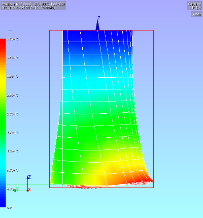
Results - displacements
In the picture the rotation of the cylinder is nicely visible. It seems that the RBE3 function does what it is supposed to do: apply an external force without additional stiffness to the slave geometry.
Asymetric mesh
The previous test was relatively easy. The mesh is symmetric. To investigate the RBE3 more thoroughly the hexahedron mesh will be made asymmetric in the xz plane, see pictures of the mesh below. In the centre the master node is visible. On this node the torsion is applied.
-
 :
: 


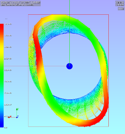
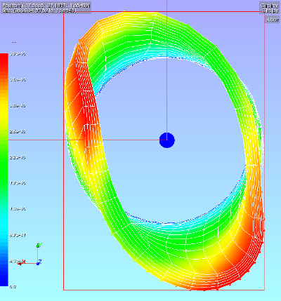
Now again applying a torsion on the master node and by the RBE3 command distributing it over the outer edge of the front face, we get the following displacements.
-
 :
: 
-
 :
: 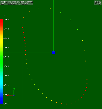


Here the results are a bit disappointing. The circulair front face is much distorted by the distributed force on the asymmetric mesh.

The reaction forces on the outer edge of the front face (Fx, Fy and the vector value) show that the vector value of the reaction forces are slightly less on the dense mesh (negative x part) compared to the coarse mesh side (positive x part). I would however expect that the reaction would deviate roughly by a factor 2 because of mesh density.
Input files for the FE Analysis and references
to be updated ...
Input files for the asymmetric mesh:
- *.py basicly creates the geometry and mesh suitable for the RBE3 constraint. The additional node and master nodes is also created here, although it gives a warning in Salome
- load by File --> load script (cntrl T in the object browser), refresh (F5) after running
- Save the mesh file by right clicking in the object browser by right clicking on the mesh name Mbcyl; select Export to MED and accept or change the default values
- load by File --> load script (cntrl T in the object browser), refresh (F5) after running
- ASTK file (*.astk, you need to edit the paths to your requirements ...)
- command file (cylinder_e.comm)
Download the files here:
Reference:
[yyyyyyyy, page zz/109]