Difference between revisions of "Contrib:KeesWouters/shell/static"
(→'''Definition of the geometry''') |
(→'''Definition of the geometry''') |
||
| Line 26: | Line 26: | ||
planar shell | planar shell | ||
Geometry: <br> | Geometry: <br> | ||
| − | L = 11.38 m <br> | + | * L = 11.38 m <br> |
| − | Thickness = 0.55 m <br> | + | * Thickness = 0.55 m <br> |
'''Loads:''' <br> | '''Loads:''' <br> | ||
[type] [group] [value] <br> | [type] [group] [value] <br> | ||
| − | Presure1 (Fbot) = 29.5e3 Pa <br> | + | * Presure1 (Fbot) = 29.5e3 Pa <br> |
| − | Presure2 (Fmain)= 25.8e3 Pa <br> | + | * Presure2 (Fmain)= 25.8e3 Pa <br> |
| − | Presure3 (Ftop) = 24.3e3 Pa <br> | + | * Presure3 (Ftop) = 24.3e3 Pa <br> |
| − | Presure4 (Fcentre1,Fcentre2)= 182.6e3 Pa <br> | + | * Presure4 (Fcentre1,Fcentre2)= 182.6e3 Pa <br> |
'''BC:''' <br> | '''BC:''' <br> | ||
| − | Lbot (DX=0.0, DY=0.0, DZ=0.0) <br> | + | * Lbot (DX=0.0, DY=0.0, DZ=0.0) <br> |
| − | Ltop (DZ=0.0) <br> | + | * Ltop (DZ=0.0) <br> |
'''Material:''' <br> | '''Material:''' <br> | ||
Concrete <br> | Concrete <br> | ||
| − | E = 32e9 Pa <br> | + | * E = 32e9 Pa <br> |
| − | Nu = 0.2 <br> | + | * Nu = 0.2 <br> |
[[Image:Geom-01-big.gif]] <br> | [[Image:Geom-01-big.gif]] <br> | ||
---- | ---- | ||
| − | Create all points and lines using: [New Entity]->[Basic}->[Point] and [New Entity]->[Basic]->[Line] <br> | + | Create all points and lines using: ''[New Entity]->[Basic}->[Point]'' and ''[New Entity]->[Basic]->[Line]'' <br> |
[[Image:Points%26lines.gif]] | [[Image:Points%26lines.gif]] | ||
---- | ---- | ||
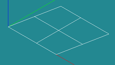
Create one big face Ftotal <br> | Create one big face Ftotal <br> | ||
| − | [New Entity]->[Build]->[Face] <br> | + | ''[New Entity]->[Build]->[Face]'' <br> |
Ftotal: Line7,Line6,Line8,Line12,Line11,Line10,Line9,Line1 <br> | Ftotal: Line7,Line6,Line8,Line12,Line11,Line10,Line9,Line1 <br> | ||
[[Image:One-face.gif]] | [[Image:One-face.gif]] | ||
---- | ---- | ||
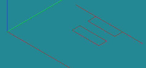
Create three wires <br> | Create three wires <br> | ||
| − | [New Entity]->[Build]->[Wire] <br> | + | ''[New Entity]->[Build]->[Wire]'' <br> |
| − | Wire1: Line3,Line4,Line5 <br> | + | * Wire1: Line3,Line4,Line5 <br> |
| − | Wire2: Line17,Line18,Line19 <br> | + | * Wire2: Line17,Line18,Line19 <br> |
| − | Wire3: Line13,Line14,Line15,Line16 <br> | + | * Wire3: Line13,Line14,Line15,Line16 <br> |
[[Image:wires.gif]] | [[Image:wires.gif]] | ||
---- | ---- | ||
Create vector <br> | Create vector <br> | ||
| − | [New Entity]->[Basic]->[Vector] <br> | + | ''[New Entity]->[Basic]->[Vector]'' <br> |
(0,0,1) <br> | (0,0,1) <br> | ||
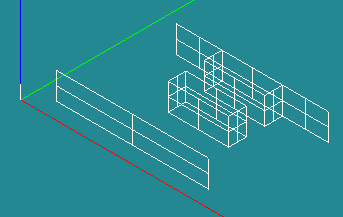
Create four extrusions <br> | Create four extrusions <br> | ||
| − | [New Entity]->[Generation]->[Extrusion] <br> | + | ''[New Entity]->[Generation]->[Extrusion]'' <br> |
| − | Extrusion1: Wire1,vz <br> | + | * Extrusion1: Wire1,vz <br> |
| − | Extrusion2: Wire2,vz <br> | + | * Extrusion2: Wire2,vz <br> |
| − | Extrusion3: Wire3,vz <br> | + | * Extrusion3: Wire3,vz <br> |
| − | Extrusion4: Line2,vz <br> | + | * Extrusion4: Line2,vz <br> |
[[Image:Extrusions.gif]] | [[Image:Extrusions.gif]] | ||
---- | ---- | ||
Revision as of 11:46, 7 March 2010
Contents
Static analysis of a shell construction
[ .... under construction .... ]
This contribution is in close cooperation with Bridge.
In this example the following items are discussed:
- preproccesing:
- definition of geometry in Salome
- partitioning of the geometry and groups
- meshing of the geometry
- definition of the groups
- (maybe: python script which makes editing much easier ...)
- static analysis with pressure or force applied on a group or nodes
- postprocessing:
- viewing displacement in Salome
- determination of stresses
- interface ASTK
Definition of the geometry
planar shell
Geometry:
- L = 11.38 m
- Thickness = 0.55 m
Loads:
[type] [group] [value]
- Presure1 (Fbot) = 29.5e3 Pa
- Presure2 (Fmain)= 25.8e3 Pa
- Presure3 (Ftop) = 24.3e3 Pa
- Presure4 (Fcentre1,Fcentre2)= 182.6e3 Pa
BC:
- Lbot (DX=0.0, DY=0.0, DZ=0.0)
- Ltop (DZ=0.0)
Material:
Concrete
- E = 32e9 Pa
- Nu = 0.2
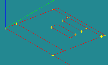
Create all points and lines using: [New Entity]->[Basic}->[Point] and [New Entity]->[Basic]->[Line]
Create one big face Ftotal
[New Entity]->[Build]->[Face]
Ftotal: Line7,Line6,Line8,Line12,Line11,Line10,Line9,Line1
Create three wires
[New Entity]->[Build]->[Wire]
- Wire1: Line3,Line4,Line5
- Wire2: Line17,Line18,Line19
- Wire3: Line13,Line14,Line15,Line16
Create vector
[New Entity]->[Basic]->[Vector]
(0,0,1)
Create four extrusions
[New Entity]->[Generation]->[Extrusion]
- Extrusion1: Wire1,vz
- Extrusion2: Wire2,vz
- Extrusion3: Wire3,vz
- Extrusion4: Line2,vz
Partitioning of the geometry
why: we need groups for loads and boundary conditions
how: we define planes
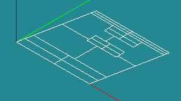
Create partition
[Operations]->[Partition]
Part_main: Ftotal,Extrusion1,Extrusion2,Extrusion3,Extrusion4
Meshing
how
tria -quad?
linear vs quadratic elements

